 The misunderstood impedance
The misunderstood impedance
The misunderstood impedance
I got a small childhood trauma by failing a correspondence course about electronics. One reason was getting fixated on computers at expense of everything else, but the major issue was not grasping the concept of impedance.
In my defense, I can say neither the course, not any material I had access to, explained the subject really well. The "epiphany" came in high school, where a good teacher and a good textbook managed to clarify the relationship between resistance, impedance and voltage drop.
We are told that resistors are passive components that "resist" to electric current. Actually, the humble resistor does two things:
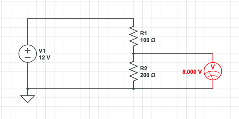
I don't like the "voltage drop" naming, because it suggests a resistor "eats" part of the battery's voltage. Actually, nobody eats nobody. The voltage between the resistor leads is of the same nature as the voltage between the leads of a battery, and it could even be used to feed another circuit.
Of course a resistor is not a generator in the strict sense. It does not generate electricity when heated with a lighter; it does not have the symmetry of a motor that works readily as a generator when driven mechanically. This lack of symmetry is what defines a resistor as a dissipative or non-conservative device.
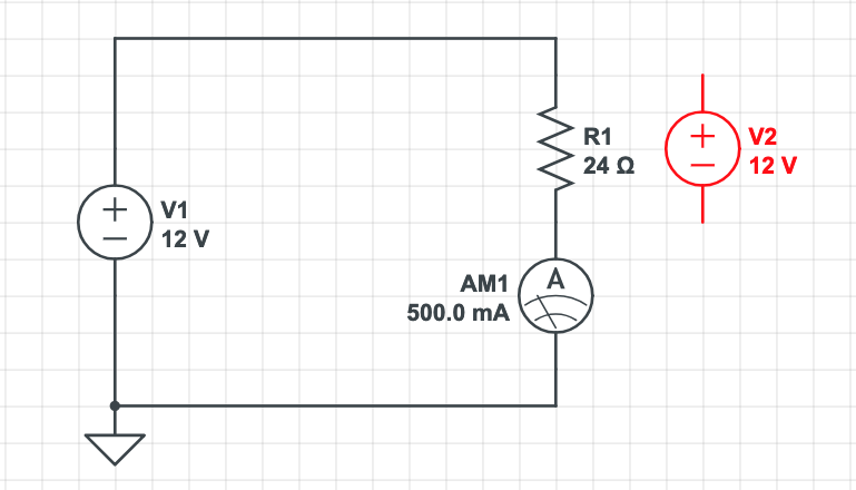
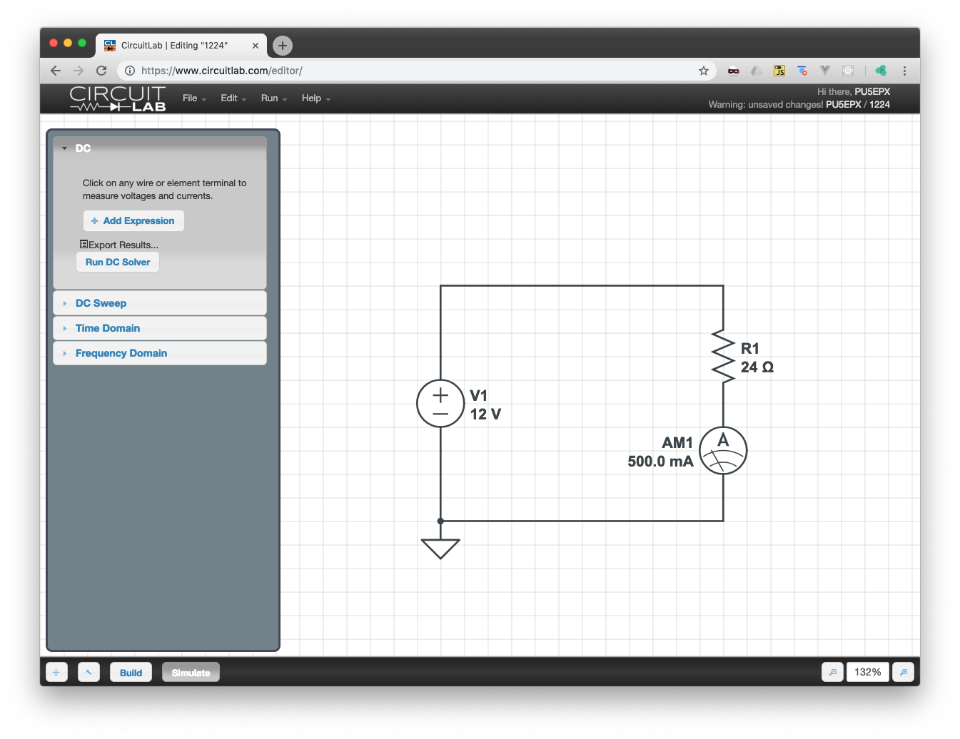
The Ohm's Law is a practical rule, but the true resistance to current is put up by the Volts, not by the Ohms. A circuit with 12V battery and 24Ω resistor can only stabilize the current at 500mA because, at this point, the resistor generates 12V too, cancelling out the battery's voltage. As long as there is a single uncompensated volt, the current increases without limit.
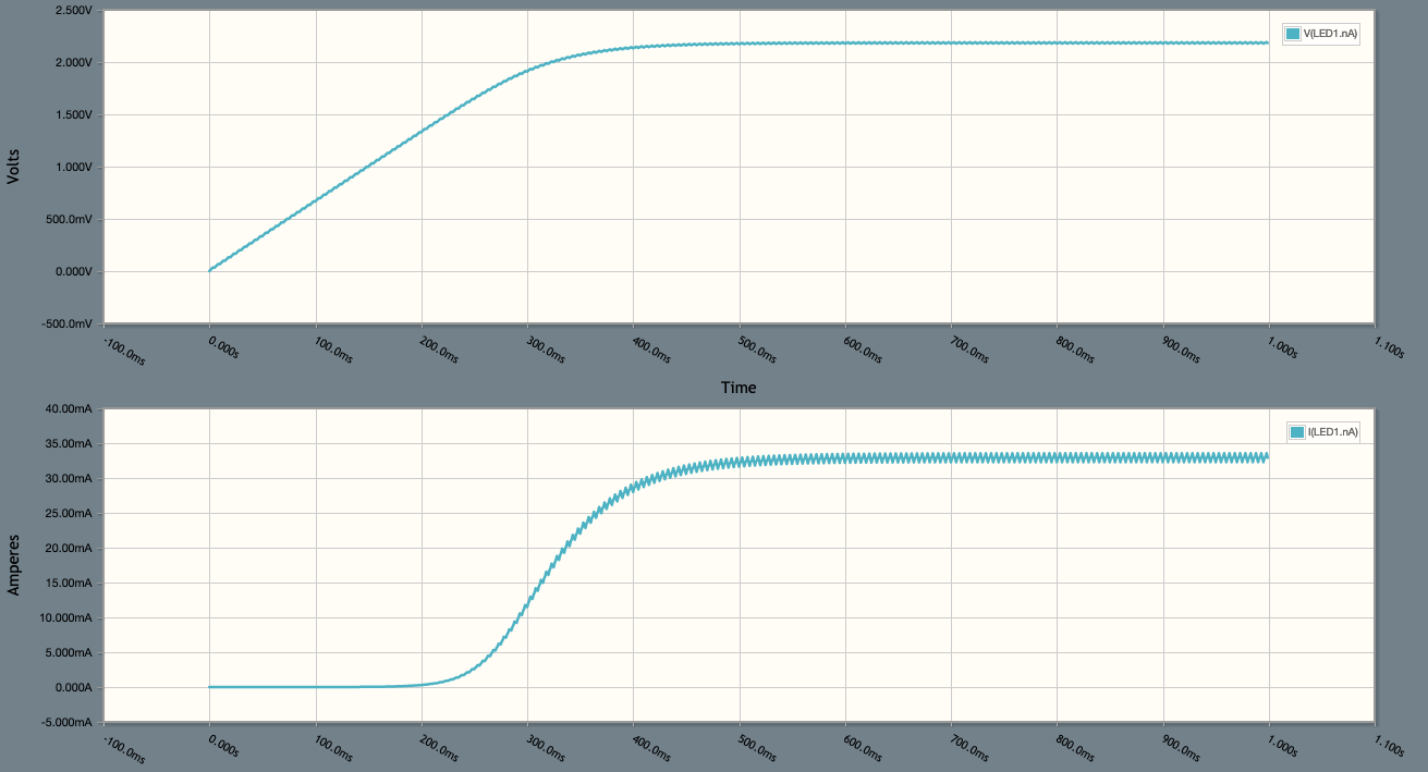
This is what happens if we connect a LED to a high-voltage source. A LED does not follow the Ohm's law: its voltage drop is almost constant for a wide range of currents. A blue LED generates 4V, a red LED generates 2V. If we connect a red LED to a 12V source, we have outstanding 10V and the current goes up the roof.
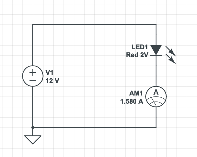
In the simulation above, the current is just 1.5A instead of "infinite" because the CircuitLab simulator knows all the characteristics of a real LED, including the internal resistance which does obey the Ohm's law. Even so, the current is 30 times too high and the LED burns up very fast.
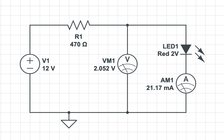
In the circuit below, there is a current-limiting resistor to handle the outstanding 10V.
By the way, the circuit simulations in the figures above were made on CircuitLab. It was the one I liked most among the ones I tested. It works on the browser, so no need to install anything and it works on every platform.
Another major point is the usage of the unit "Ohms" in contexts where resistors, resistance and heat dissipation do not exist at all.
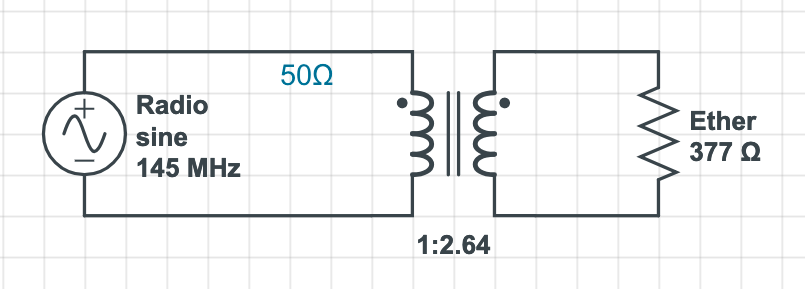
An extreme example is the "vacuum radiation resistance" or "vacuum impedance", valued around 377Ω. What does it mean. As you might suspect, a radio wave or a light ray traveling on space suffers no losses, no voltage drop, and no dissipation.
The electromagnetic wave has two components: a variable electric field (measured in Volts-meter) and a variable magnetic field (expressed in Amperes-meter). When the wave is traveling in vacuum, the proportion between the two is around 377. The unit of this number is "Ohms" because we are dividing Volts by Amperes, but it is kind of an abuse of notation.
So, this is the idea: "Ohms" can show up every time there is a relationship between voltage an current, or between electric field and magnetic field, with or without heat generation as a byproduct.
Impedance is expressed in Ohms, but it may be of many types. It can be dissipative, transformative or reactive.
A 5Ω resistor has 5Ω resistance and 5Ω of dissipative impedance. Resistors are indeed simple; their impedance is always equal to resistance.
A motor is more complex, since part of its impedance is transformative. Suppose a circuit with 12V source, a 75% efficient motor and a 500mA current, as the model below.
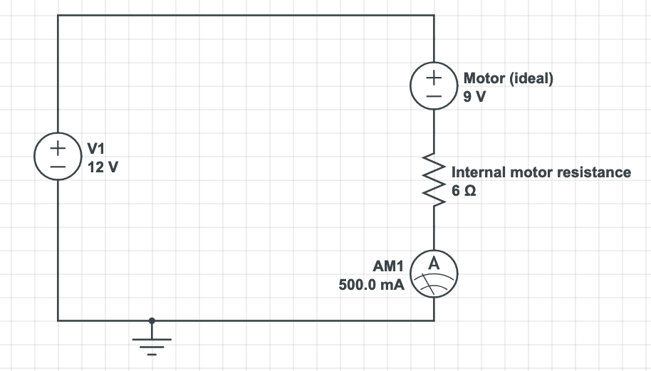
The total impedance of the motor above is 24Ω, since it can limit the current the same way as a 24Ω resistor would. But 75% or 18Ω of this impedance is conversion of electric energy into mechanical motion. The remaining 6Ω are generating heat.
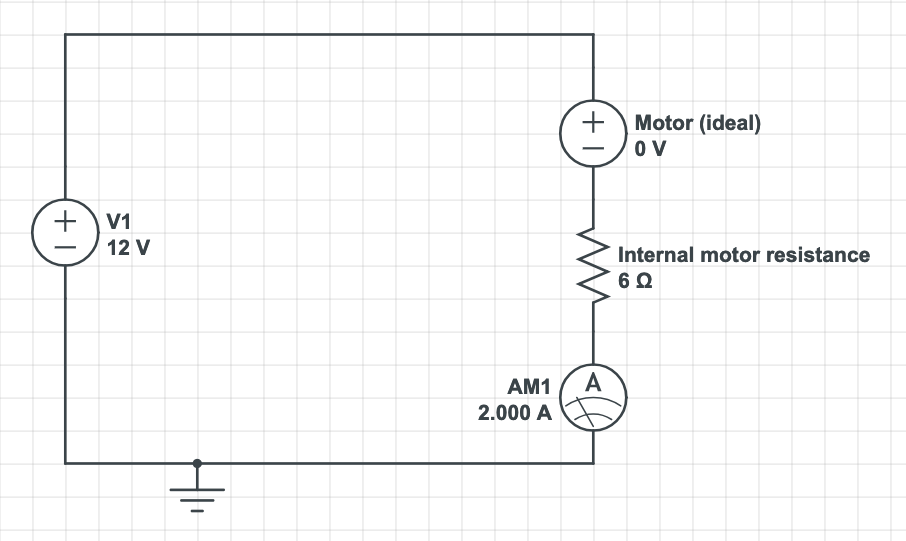
It is noteworthy the transformative impedance of a motor changes all the time, depending on RPM. At startup, it is zero, and the current is limited only by the 6Ω internal resistance.
An antenna also possesses transformative impedance. For example, the dipole antenna (with two wires or rods) has a 73Ω impedance at optimum operation frequency. A radio transmitter, which is the generator, "sees" a dipole antena or a 73Ω resistor as similar loads. The "useful" impedance of the antenna, which can generate electromagnetic waves, is known as radiation resistance.
Apart from the fact the "useful" impedance of antennas and motors change a lot in operation, from a purely electrical point of view it behaves exactly the same as dissipative impedance. Both convert electricity to other forms of energy, and that energy leaves the circuit for good. From now on, we call both "resistance".
One more thing to talk about: reactive impedance. This one is tough.
From the point of view of a DC (direct current) circuit, a coil is just a bunch of wire, hardly different from a short-circuit. Things change in AC (alternating current) circuits. Under AC, the coil becomes reactive: it absorbs energy and gives it back at every cycle.
Likewise, a capacitor does not let any DC current to pass, but it becomes reactive under AC, storing and releasing energy.
In the course of absorbing and returning energy, these components generate a voltage opposing the current. Therefore, they also "resist", in their own terms, and this kind of impedance is also measured in Ohms.
In electrical systems, devices whose device is partly reactive are called reactive loads. They are almost always undesirable. The reactive impedance does not spend energy by itself, but the current going back and forth is dissipated on transmission (wiring, connections, plugs, transformers, etc.).
For example, suppose an apparatus with 22Ω reactive impedance. If you plug it in a 220V socket, there will be a 10A current (220 divided by 22). The apparent power is 2200VA (220 times 10), but the real power is zero, since the current goes back and forth 120 times a second. The electricity bill does not increase because the meter keeps moving back and forth.
Now, let's assume the transmission losses between the powerplant to your house are 10%. In a first approximation, energy going back and forth is 100% lost after 10 trips. It cost money to be generated, just heated up air and nobody will pay for that.
Of course they utilities wouldn't leave it like that. They punish consumers whose power factor is low — that is, with a high proportion of reactive loads. To avoid this, big consumers install power factor correcting equipment. If there are too many inductive loads (motors, magnets) a bank of capacitors can help since it is reactive in the opposite way. With this equipment, the consumer impedance feels non-reactive to the utility.
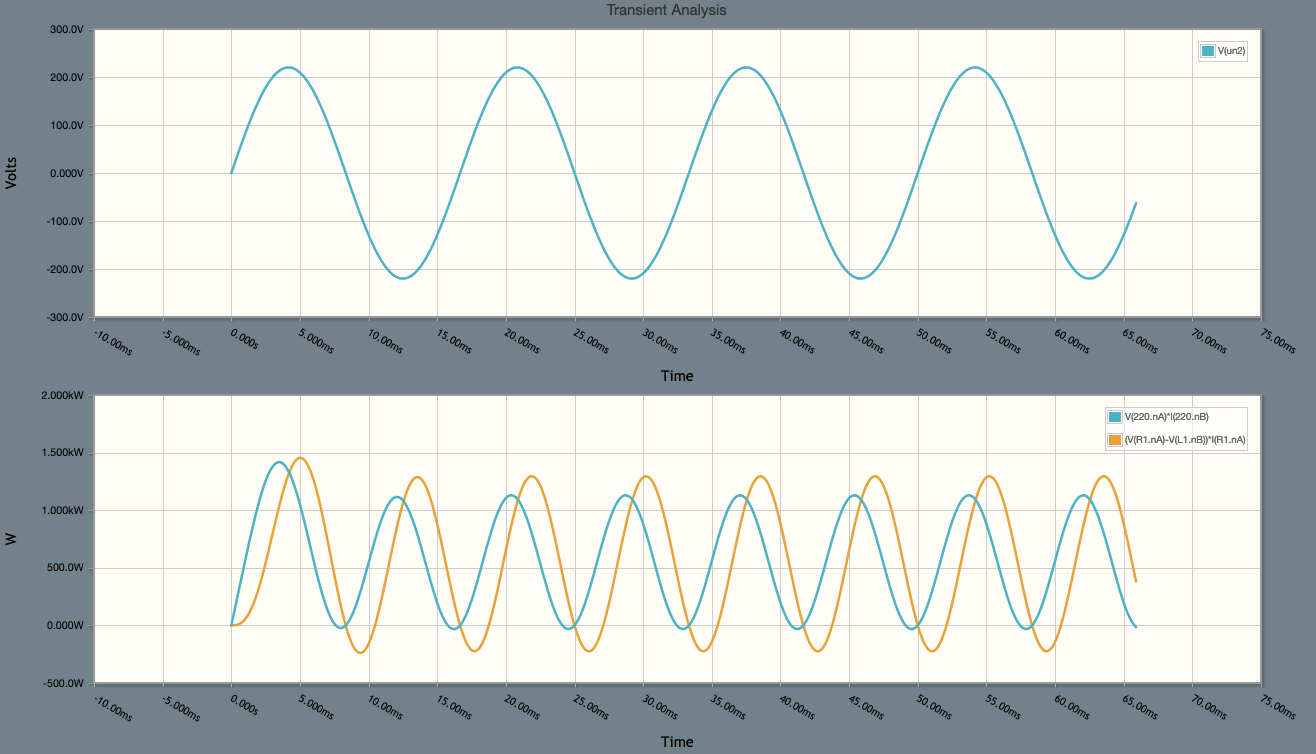
Let's see an example of correction for a partially inductive load:

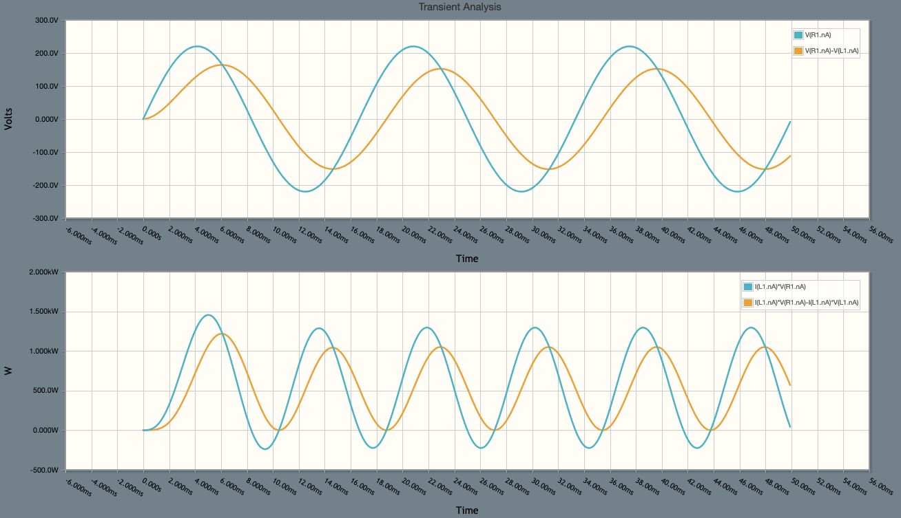
In the simulation above, we see the voltage drop on resistor (orange, above) is delayed and weaker in relation to the generator voltage (blue, above). This reflects on the power. The effective power (orange, below) is smaller than the apparent power (blue, below). The apparent power dips below zero during part of every cycle; this is the moment when the inductor is returning energy to the grid.
In the following circuit, we try to correct the power factor with a series capacitor.
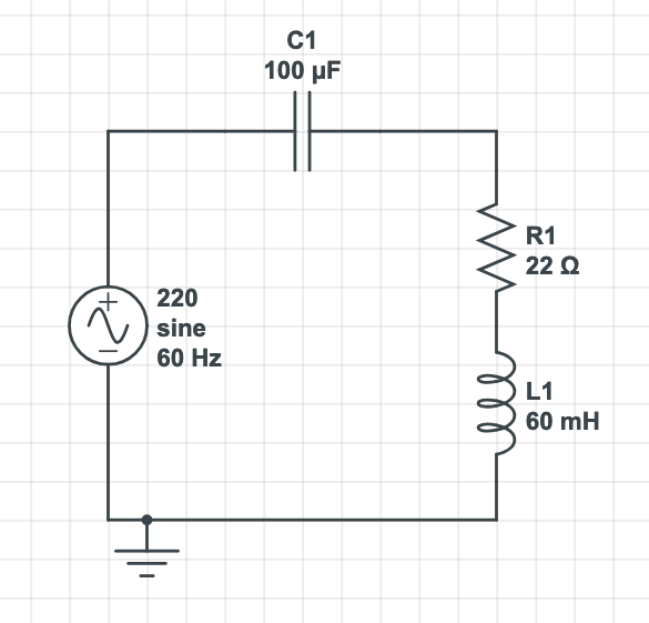
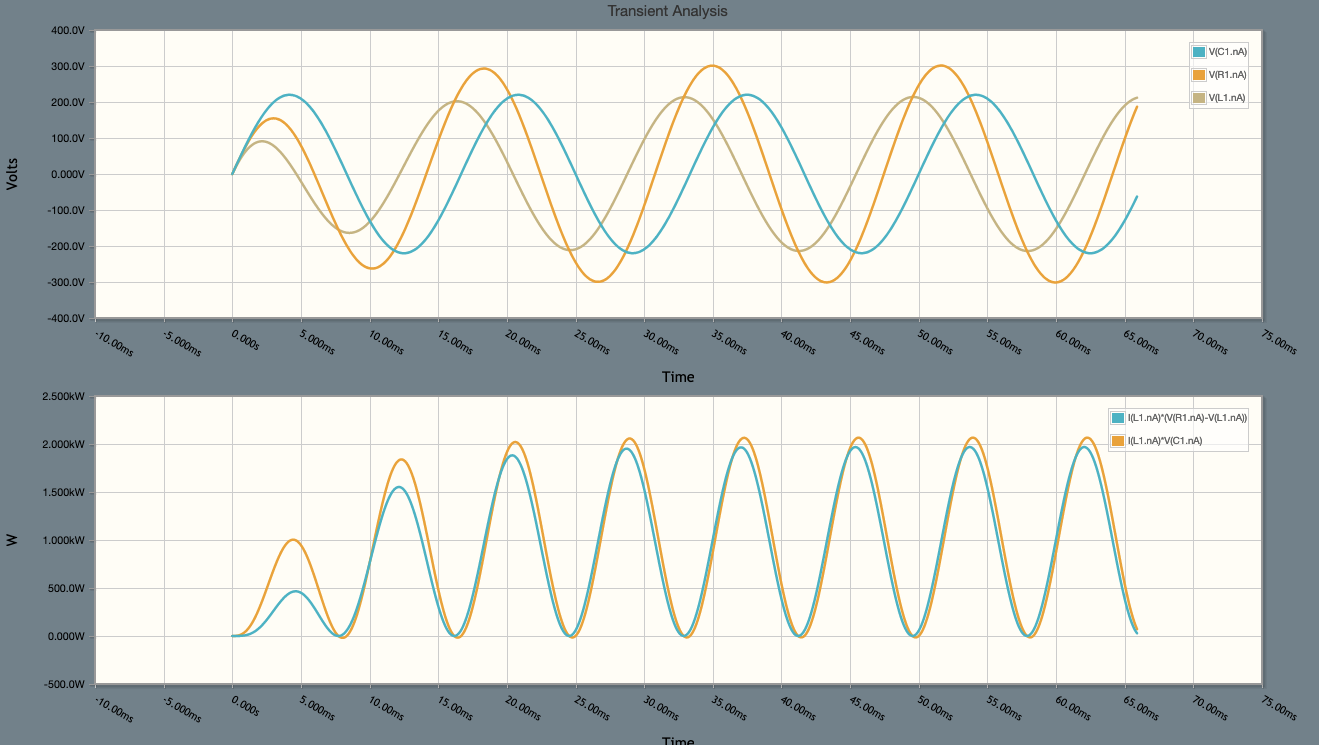
With the right series capacitor, the real power is almost equal to the apparent power. One collateral effect is the higher voltage forced upon the resistive load, higher than grid's voltage, with peaks over 300V. This forces the load to handle all the expected power (2000W = 220V times 10A). This can be good or bad, depends on the application. Series correction is more common in radiofrequency. In common electric circuits, parallel correction is more often used:

From the point of view of the generator, the apparent power (blue) almost does not dip below zero, so the capacitor is almost ideal. On the other hand, the load's apparent power (orange) still :q has big excursions below zero. At least the power is returned to the nearby capacitor, not to the grid. The real power (blue) stays well below 2000W, because the parallel circuit does not force higher voltage upon the load.
The reactive impedance is not always a bad thing. For instance, it does the "magic" of limiting current without dissipation of energy.
For example, the ballast of older fluorescent lamps used to be a simple coil, actually an autotransformer with two tasks: increase the voltage for easy startup, and limit the current once the lamp is lit. (Just like a LED, a fluorescent lamp can't control the current by itself.)
The circuit below feeds a LED from the grid, without a transformer and without dissipation, using just a capacitor as current limiter.
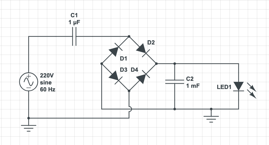
The small capacitor limits the current, while the big one stores energy so the LED stays lit without flicker. Let's simulate the circuit:
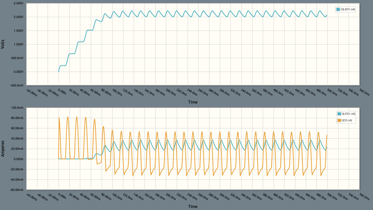
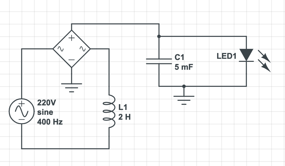
The following circuit does a similar thing, using an inductor instead of a capacitor. It is not the best choice since the inductor must be large, even when the generator is 400Hz AC.
In the following simulation, note how the LED current builds up only when the voltage is near 2V.
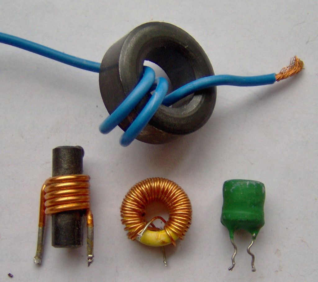
Inductor is a device which generates a magnetic field when crossed by a current, and vice-versa. A simple wire is an inductor, if small-valued. In general it takes many turns of wire around a core or toroid of some material of high magnetic permeability, in order to get significant inductance. Transformers, motors, generators, electromagnets, etc. are built upon inductors.
The impedance of an inductor, known as inductive reactance, can be calculated by the following formula:
Ω = j.2.π.f.L
where "L" is the inducance in Henries (itself a function of diameter, number of turns, core material, etc.) and "f" is the frequency of AC current. A coil fed with DC current has zero impedance.
We will postpone the explanation of "j". For now, ignore it.
An inductor is reactive since it converts electricity to a magnetic field. When the current stops, the magnetic field collapses and is conveted back to electricity. In theory the conversions are lossless. The symmetry means it is a conservative component.
If the magnetic field is somehow "stolen" from the inductor, naturally the electricity invested on it can not be recovered. This effect reduces the reactive impedance. This is what happens in a transformer: the primary inductor's field is absorbed by the secondary inductor, as long the secondary has a load. On the other hand, if the secondary has no load, there is no circuit, it can't function as a coil, and the primary is left alone to work as a pure inductor.
It is expected an unloaded transformer does not let current pass through. To achieve this, the primary coil's inductance must be strong enough so the reactive inductance is high. Since the reactance is proportional to frequency, higher AC frequencies allow for smaller, ligher transformers. That's why aircraft use 400Hz AC circuits instead the typical 50 or 60Hz.
Capacitor is a device which converts electricity to an electric field and vice-versa. An elementary capacitor can be built with two plates of conductive material, separated by glass, air or some other dielectric insulator.
The bigger the plate area and/or the thinner the dielectric, the bigger the capacitance. A simple pair of wires running in parallel is a capacitor, albeit of a very modest value.
The reactive impedance of a capacitor, known as capacitive reactance, follows this formula:
Ω = 1 / (j.2.π.f.C)
where "C" is the capacitance in Farads, "f" is the frequency of the AC current fed into the capacitor. As we did for the inductor, let's ignore the "j" for now.
The relationship between capacitive reactance and frequency is inverse: a capacitor has infinite impedance in DC, and resists less and less to AC current as frequency increases.
The capacitor is reactive because, likewise the magnetic field, the electric field can be converted back to electricity with virtually no losses.
When a resistive load is fed with AC, voltage and current are always in phase. If voltage is positive, current is also positive. If the first is negative, so is the latter. The product of both is always positive, meaning the energy transfer is always one-way, from the source to the load.
In the case of a reactive load, this is no longer true. Given a purely inductive load, current lags 90º behind the voltage. In a purely capacitive load, current leads voltage by 90º.
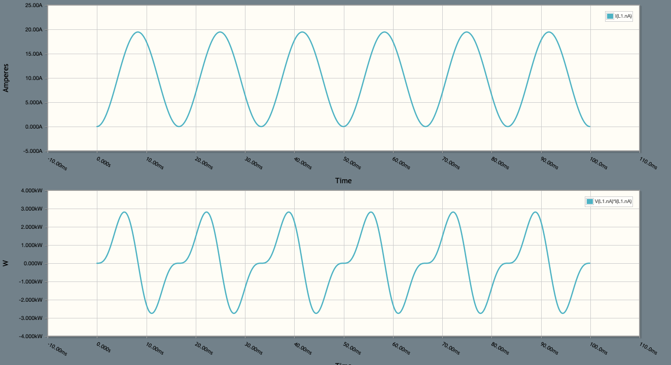
In some figures found in the section about reactive impedance, someone may have noted the power waveforms are out-of-phase in relation to voltage. Here is the current and voltage of an AC circuit with just an inductor as load:
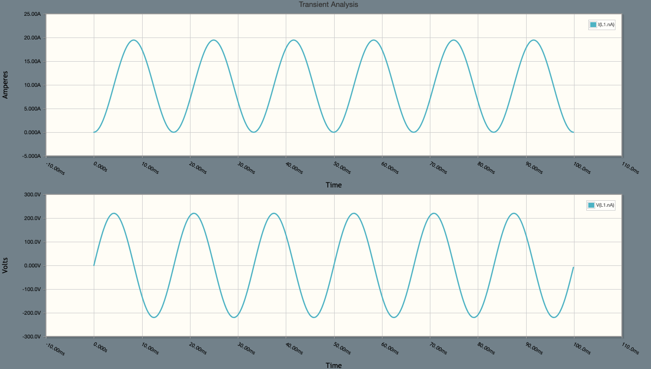
In the chart above, voltage and current have the same sign half the time. At these moments, power is positive, meaning it flows from the grid to the inductor. In other moments, voltage and current have opposite signs, power is negative, meaning it flows from the inductor back to the grid. The overall sum is zero: a purely reactive load neither sources nor sinks energy, and does not do anything useful.
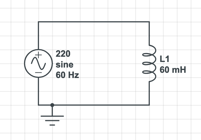
In the example below, the load has almost equal amounts of resistance and reactance when fed with 60Hz AC. In this case, the phase delay is around ±45º.
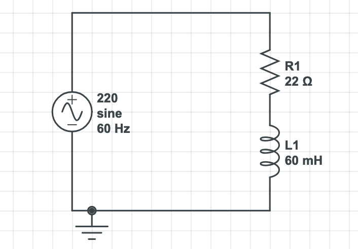
Remembering the formula: an inductance of 60mH fed with 60Hz AC generates an inductive reactance of 2π×60×0.060 = 22.8Ω aprox.
Now it's time to explain those J's in reatance formulas.
As mentioned before, inductive and capacitive reactances are opposite and can be combined to cancel each other e.g. to correct the power factor. An inductive reactance of 32Ω in series with a capacitive reactance of 10Ω is equivalent to an inductive reactance of 22Ω.
Moreover, reactances are "imaginary" impedances since they can't consume energy, they just absorb and return it. They need to be handled separatedly from the "real" impedances that do consume energy.
Since the reactive components cause a phase lag between phase and current, reactive and non-reactive impedances are like apples and oranges, they can't simply be added up, but can be part of a fruit salad.
For example, a load with reactance +22Ω (positive=inductive) and 18Ω resistance is not equivalent to a 40Ω resistor. The whole impedance is the vector sum: 28.4Ω. The current lag is equal to the vector angle: 50,7º.

Given all these facts, it is extremely convenient to express a mix of reactive and non-reactive impedances as a complex number. In the example: 18+22j. The total impedance is the modulus of the complex number, the phase lag is the angle.
Another advantage of using complex numbers is being able to use the same formulas to simplify series and parallel circuits. Let's calculate the total impedance of a circuit:
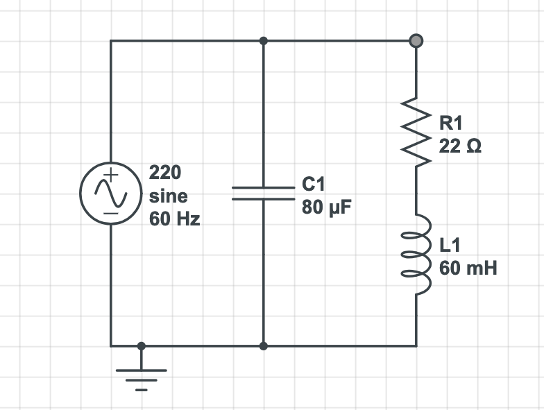
The resistor impedance is purely real 22Ω. The inductor impedance is purely imaginary. By the formula j.2π.f.L, we get +22.6jΩ. The total impedance at the right branch is a plain sum: 22+22.6jΩ.
The capacitor has a reactance of 1/(j.2π.f.C) or -33jΩ. Using the formula to simplify two parallel resistors (R1.R2)/(R1+R2), we have
R1.R2 = (22.0 + 22.6j) * (0 - 33j) = (745.8 - 726j)
R1+R2 = (22.0 + 22.6j) + (0 - 33j) = (22 - 10.4j)
(R1.R2)/(R1+R2) = (40.5 - 13.9j)
The result (40.5-13.9j) is compatible with the simulation. The imaginary part of the whole circuit is less than the inductor's reactance, but it's not quite zero. It would take a 60µF capacitor to zero the overall imaginary impedance.
In electronics, the "impedance matching" thing crops up very often.
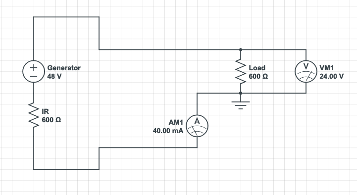
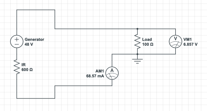
In the original sense, the idea was to maximize the power transfer. For example, if the internal impedance of a generator is 600Ω, the optimum load is 600Ω. Higher load impedance reduces the current, lower impedance increases the dissipation within the gererator.
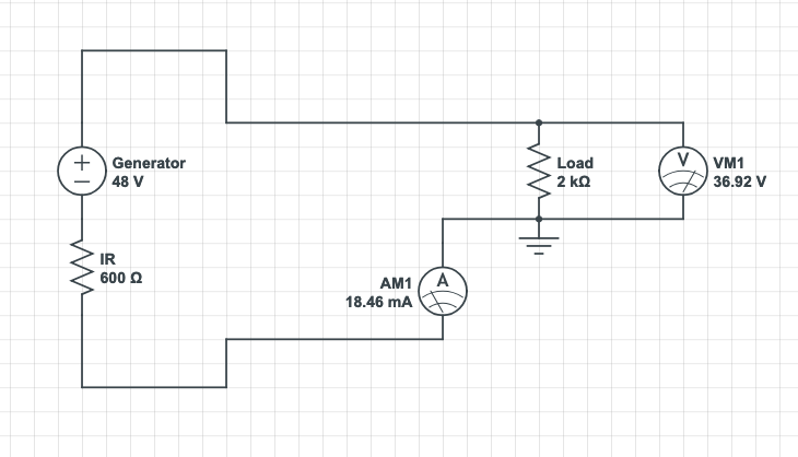
When we just want to transfer information (audio, video, data), not energy, we are normally interested on the voltage only. In this case, a high-impedance load is fine.
On the other hand, it is difficult to justify a circuit where the load as lower impedance than the gererator, since both the power and the voltage are higher inside the generator, often burning it.
In order to avoid the bad situation above, everything goes, even matching the load with resistors. The power and voltage transfer to the load is still bad, but at least the generator is spared.
It is also possible to match impedances using a transformer. The only downside is, transformers work only with AC power.
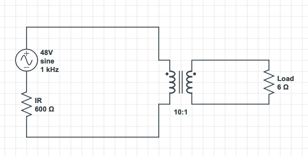
Tube audio amplifiers often use a big output transformer to match impedance with the loudspeakers. Tubes or valves like high voltage and can only carry small currents, while loudspeakers are low voltage/high current devices. In this case, "matching impedances" means matching the needs of different parts of the circuit.
Semiconductor audio amps have very low internal impedance, it is often taken as zero. The output voltage is already compatible with louspeakers. Yet, the loudspeakers must have a minimum impedance in order to limit the current. In this case, "matching impedances" means limiting the power transfer, not maximizing it.
In short, impedance matching has been chosen to:
In all cases above, using a load with impedance too high should not burn anything, it just reduces the performance.
But there is a fifth case where the load impedance must be around the optimum, it can't be higher and can't be lower.
In general, we learn electronics under the assumption the circuits are in a general state of equilibrium — as if they were a huge water circuit of communicating vessels, where we add or take water using an eyedropper, there are no sudden disturbances and we can take for granted that water level is the same everywhere. This is true even for AC circuits, as long as the frequency is low enough.
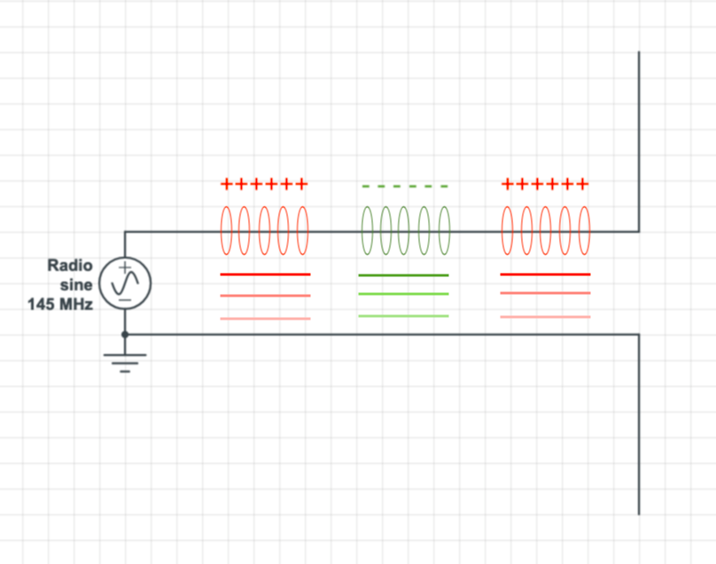
As the line lengths and/or the frequencies increase, this general equilibrium is hindered. By and large, when the line is longer than 1/10 of the AC wavelength, voltages and currents will be very different along different parts of the circuit. The propagation becomes wave-like, since the electric field has a wave-like shape along the circuit, and propagates as a wave.
Making an analogy with ropes. Let's say you build a long cable by tying together ropes with dissimilar diameters and/or weight per meter. Is it a problem? Depends on how you transmit power using this cable. If you pull slowly and steadily, everything will be fine. If you pull in a vibratory way, or whip the cable, there will be reflections at cable joints.
Ok, but an electric wire is not a rope, so how exactly the reflection can occur?! It happens because, at the point of impedance change, there is a sudden change in the relationship between voltage and current, or between electric and magnetic field. This will create a standing field at that point, which work as a secondary generator.
In the extreme case of an open transmission line (without a load), the electric field accumulates at the far end like a spring, and comes back when voltage permits. The reflected signal is the same sign as the original. Note how different this is from a DC open circuit in steady state, where current is zero at every point.
The other extreme case is a short-circuit as the load. In this case, the sudden drop of voltage creates a steady magnetic field which induces an inverted signal. Again, it works very differently than a DC short circuit in steady state.
Nowadays there is equipment that allows to watch these phenomena happen directly on an electric circuit, we don't even need to resort to analogies to rope waves or water waves. This video shows the waves going back and forth from the moment a DC circuit is turned on, until reaching equilibrium.
But, do these phenomena happen in AC mains? Mains frequency is low, but it is not DC. The answer is: it depends on line length and line characteristics.
The length of 1/4 wave at 60Hz is 1250km, so the eletromagnetic effects start to take place when the line has a length at this order of magnitude. The rule of thumb is that aerial power transmission lines shorter than 80km are deemed "short" and can be modeled as simple inductors; the capacitance can be ignored. From the point of view of your house, the "generator" is the nearest pole transformer. In such a short transmission line, the behavior is just like DC.
In high-capacitance power lines e.g. underground lines or very long aerial lines, the impedance mismatch starts to show up through the Ferranti effect that increases the voltage when the load is too light (and decreases when it is too heavy). In these cases, it is important the transmitted power is neither to high nor too low i.e. the load impedance should match the line impedance.
The reactive nature of a power line, and its affect on voltage, is a problem but it is also a tool, since it allows for voltage regulation by simple insertion or removal of compensation reactances at substations. It is a cost-effective and lossless method that is not available for e.g. DC power lines.
Insulated HV cables are similar to coaxial cables, but much more complicated. Frequency is low but the electric field and the transmitted power are huge, so even a "leakage" of 0.0001% would cause a spetacular failure.
When the transmission line is long, it is not sufficient to match the impedance for the load. The line itself must "seem to have" the same impedance. Otherwise, there will be reflections.
Characteristic impedance is this apparent impedance of a line. Coaxial cables tend to have either 50Ω or 75Ω. If a 50Ω cable had infinite length, the cable itself would be the load, and the real impedance of such a load would be 50Ω.
Since lines are nowhere near of infinite length, ther actual impedances are around zero. The characteristic impedance is useless to limit the current. It is just the relationship between the electric field (V.m) and the magnetic field (A.m) created within the cable.
It is noteworthy the electric field within the cable is created by the capacitance between conductors, and the magnetic field is created by their inductance. Therefore, the characteristic impedance can be calculated given the cable's capacitance per unit length and inductance per unit length.
The funny thing is, the characteristic impedance exist because of the reactive "components" embedded in the cable, but it is not reactive by itself, at least in a lossless cable.
Matching the impedance between cable and load, or between cable and generator, can be carried out using the same techniques that would be used to match generator and load directly (transformers, baluns, etc.). In ham radio most cables and radios are both 50 ohms, so we only need to worry about the impedance of the antenna.
In very long or underground high-voltage power lines, it is also necessary to take its characteristic impedance into account. It is generally expressed as "surge impedance loading", which is a power level that corresponds to a well-matched load impedance. During hours of low power transmission, the electrical system may even turn some lines off to avoid big mismatches, that could increase the voltage too much at load side due to Ferranti effect, possibly exceeding the capability of some insulator.
The example of power lines gives us another information: the effects of mismatched impedance do not show up suddenly at some specific frequency, power level, and/or line length. They can vary from negligible to mild to severe, depending on all three factors.
In amateur radio, most transceivers ask for a 50Ω antenna, so we use a 50Ω coaxial cable and a dipole antenna with impedance of... 73Ω. Is this a problem? Do we need a balun in this case?
In fact, some signal (18%) is reflected back due to the step between coax and antenna. But, when the reflection reaches the transceiver, it is reflected forward again. (The transceiver takes a 50Ω antena, but nobody said it has to have 50Ω internal impedance.) The reflections go back and forth until all energy is either radiated by the antenna or dissipated by the cable.
The reflected signal may hurt the transceiver, or not. It depends on the project. Modern devices accept a wide range of antenna impedances, and therefore tolerate reflections in this range, because the antenna of e.g. an HT changes all the time due to external factors. Just putting the hand or the face near the antenna is enough to make its impedance swing.
The combination of generated and reflected waves creates a standing wave along the line. It does not mean much by itself, despite the vast folklore around it. It is importante because it is easy to measure.
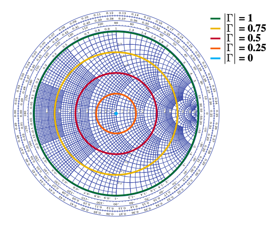
Given a measured SWR (Standing Wave Ratio), it is possible to formulate some hypothesis about the impedances and try to correct them. Unfortunately, the SWR can't tell in which direction the impedance is wrong. Among real and complex impedances, all possibilities lie on a circle. There is even a diagram, the Smith chart, that helps do trace this circle.
The obsession of hams about getting 1:1 SWR is a folklore by itself. A 2:1 SWR means only a signal refleciton of 11%, not 50% as the ratio suggests. And, as said before, the reflected signal is reflected again towards the antenna, so it is not "lost", much less absorbed by the radio.
Some "solutions" to lower the SWR e.g. using a longer transmission line, just add resistance which dissipates energy in both ways. It makes SWR look better when measured at radio side, without fixing the original impedance mismatch.
One legitimate reason to lower the SWR is avoiding the losses due to cable resistance. A signal reflected ten times before taking off suffers this loss ten times. Also, signals that carry a lot of data, e.g. TV or high-speed digital, may be garbled by the delayed reflections. Lower the SWR is a must for them, even at cost of higher losses.
There is an endless discussion about how, or if, the SWR can burn a radio by itself. Many say yes, given the sum of incident and reflective waves' voltages can reach high voltages, well above the working voltage of the device.
Others say it can't happen, a high SWR is just a symptom; the thing that really burns the radio is the mistuned antenna. Unlike an audio amplifier, a radio transmitter has a tank resonant circuit. Without a tuned load, the energy accumulates and dissipates on this very circuit, for which it is not built.
In modern devices, power is automatically reduced when a high SWR is detected. Lowering the SWR may be necessary simply to "convince" the radio to produce its rated power.
We've talked about many things, like the concept of characteristic impedance is more important in radio frequencies. Having talked about RF, now we need to take a look at the antennas.
Antenna is a device which generates electric and magnetic fields, in a way both fields can combine and propagate as electromagnetic wave. In the near-field region of the antenna, both fields can still be observed, and used, separately. (Transformers and RFID readers are near-field devices.)
The antenna also "matches" the vacuum impedance (377Ω) with the circuit's impedance, as if it were a transformer. We can say, for example, that a dipole antenna (73Ω) embeds a 1:2.25 transformer.
As we've seen before, the vacuum impedance is the relationship between the electric and magnetic fields that together make an electromagnetic wave. But does that mean the electric component is 377 times stronger?
The answer is no; this is just a consequence of the units we employ (V.m and A.m). On average, every field carries 50% of the wave power. One pound of lead weighs as much as 453g of cotton.
It is true that electric fields are easier to detect and measure. Most antennas are sensitive to the electric field, case of the dipole. But there are magnetic antennas that work equally well.
An antenna can be modeled after an RLC circuit, since it generates electric fields like capacitors and magnetic fields like inductors. The resistor models the radiation resistance as well as the losses. The frequency of resonance is the point where L and C reactances cancel out, leaving only the radiation resistance.
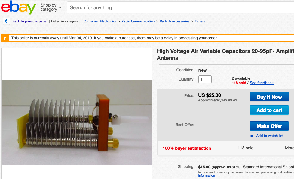
The short loop or magnetic antennas are literally an LC circuit: they have a true variable capacitor for tuning, and the loop is a 1-turn inductor. Those old AM portable radios have internal ferrite antennas, whose inductor is made by countless turns of thin wire.
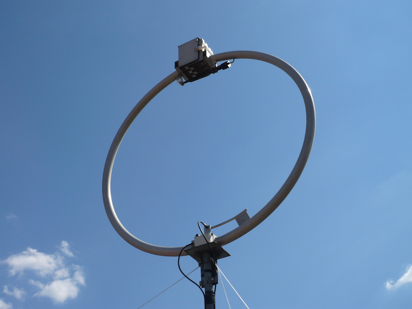
In a magnetic antenna, the inductor-like part is responsible for irradation and/or reception. This is possible since varying a magnetic field generates an electric field, and the inductor generates both. But the inductor must have size and format that entices propagation, it is not enough to have the correct inductance.
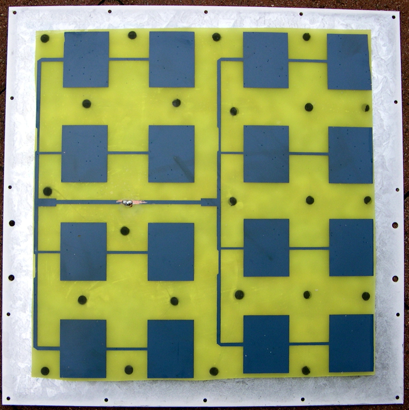
In "patch" or planar antennas, the opposite happens: the capacitor-like part is the antenna proper. This works because varying an electric field creates a magnetic field (Maxwell's big discovery). The capacitor's size and format must be appropriate for radiating, while the inductance is there just for tuning.
At non-resonant frequencies, the total impedance can increase or decrease. At 0Hz (DC), a dipolo is an open circuit while a folded dipole or a loop is a short-circuit. At non-resonant high frequencies, the impedance may be complex, with capacitive or inductive reactance in the mix.
A reactive antenna is undesirable. As we've seen before, a reactive load absorbs and returns energy at every cycle — yet another source of signal reflection. It would be great if the antenna had radiation resistance of 50Ω, matching most transmitters and coaxial cables.
Unfortunately, almost every practical antenna has impedance different from 50Ω and also has some reactive impedance. The solution is to use a transformer ("balun") to match the total impedance and/or a tuner to add inductance or capacitance that compensates for the reactive antenna. The tuner is analog to the power factor correction circuits we've talked about.

A balun is not a big source of losses, but the tuner can be. A reactive antenna does not cease to be reactive because of the tuner. Just the signal reflections are confined between the tuner and the antenna. If the antenna is severely mistuned, energy is dissipated while it goes back and forth. Ideally, the antenna should be almost "there", the tuner just makes the fine adjustment.
In some applications, the antenna must not be big, so the tuner has to work overtime. A bad antenna is still better than no antenna. Many portable antennas (for cars, HTs) are "short" and have capacitive reactance, and have an embedded inductor to compensate for. Those antennas that look like springs distribute that inductor throughout the length.
This makes portable devices viable, but the signal is reflected many times inside it, and the efficiency is always less than a plain dipole.
"Balun" is synonym of impedance transformer, but the name is not proper. A "pure" balun just adapts an unbalanced line to a balanced antenna or vice-versa. In practice, though, a balun is expected to do both tasks.
A coaxial cable is an unbalanced line. In theory, the outer brain is grounded and the energy flows entirely thorugh the inner conductor. The cable can't irradiate because the outer braid shields the inner core from the external world.
Computer network cables, telephone wires, the 300Ω flat cable your grandpa used to connect the TV to the Yagi antenna, those are all balanced lines. They are not shielded, but do not radiate and don't pick up noise (ideally) because the conductor pairs carry equal and opposite currents.
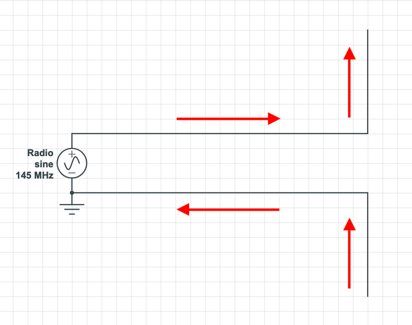
A dipole antenna is a balanced antenna. By connecting it to a coax cable without a balun, the outer braid is forced to carry current, causing the cable to radiate. If the cable irradiates, it becomes part of the antenna and changes all radiation characteristics.
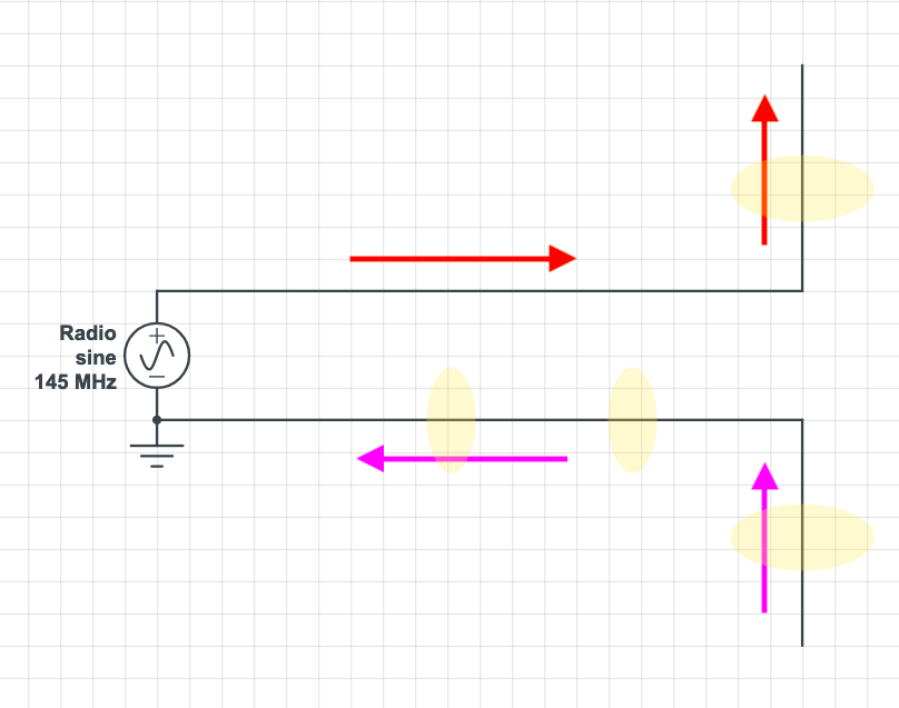
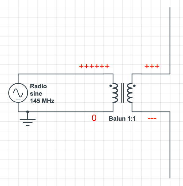
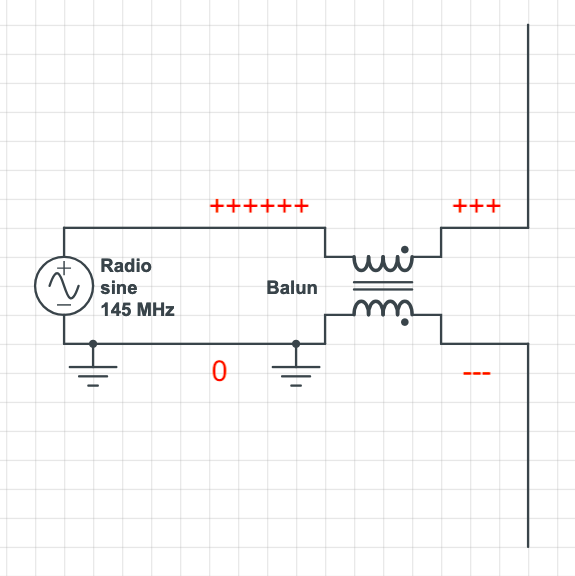
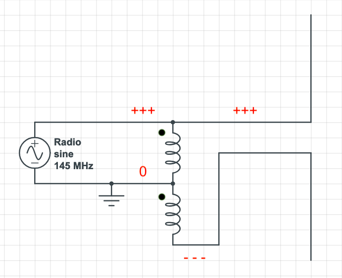
The balun adapts the coax to the antenna, blocking any return currents through the shielding braid. There are many ways to create a balun. The most kosher would be a 1:1 transformer; a different transformer ratio can be used if we need to match impedances as well.
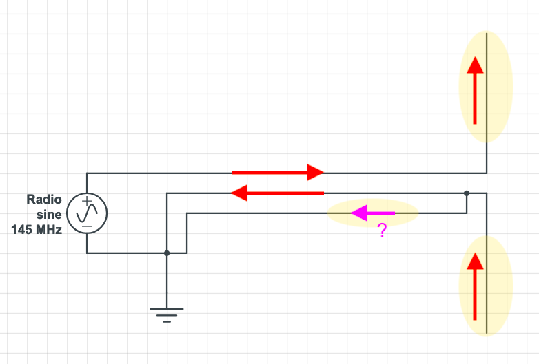
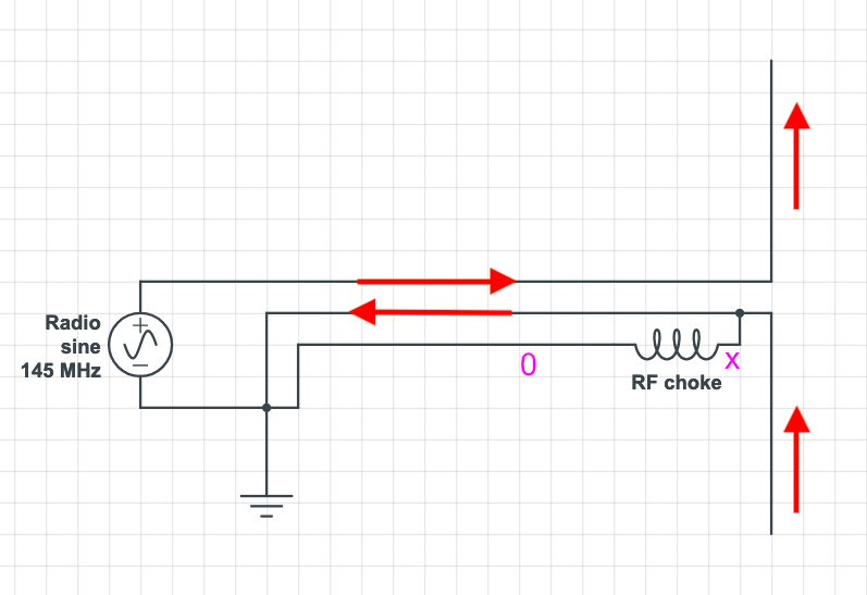
As frequencies go higher, things get simpler. A simple RF choke is enough to block the return currrent. One just needs to make a small coil with the coax cable itself, using an air core or ferrite core, depending on frequency.
This inductor has no effect on the inner core current, it can only add reactive impedance to currents on the outer braid, thanks to the shielding effect of the braid.
Is a balun really necessary? A lot of people just connects the coax to a dipole antenna, no balun in sight, and everything seems to work well.
According to some texts, the underlying reality of the "return current" is a bit more complex. The coax braid is not current-free as most say. Case is, in the optimum case, the current flow through the inner layer of the braid, which is still shielded by the outer layer, and the latter should indeed be current-free.
When the coax is connected to the dipole antenna, one side is connected to the whole shield braid, and the return current is divided, God knows how. If the current prefers the inner layer, everything is fine. If a substantial part of the current chooses the outer layer, there will be trouble. Baluns and RF chokes block the currents that try to flow through the outer layer.
SWR myths and mysteries. By Andrew Barron ZL3DW
Another Look at Reflections. By: M. Walter Maxwell, W2DU/W8HKK