 KMK87: a Python-powered full keyboard
KMK87: a Python-powered full keyboard
KMK87: a Python-powered full keyboard
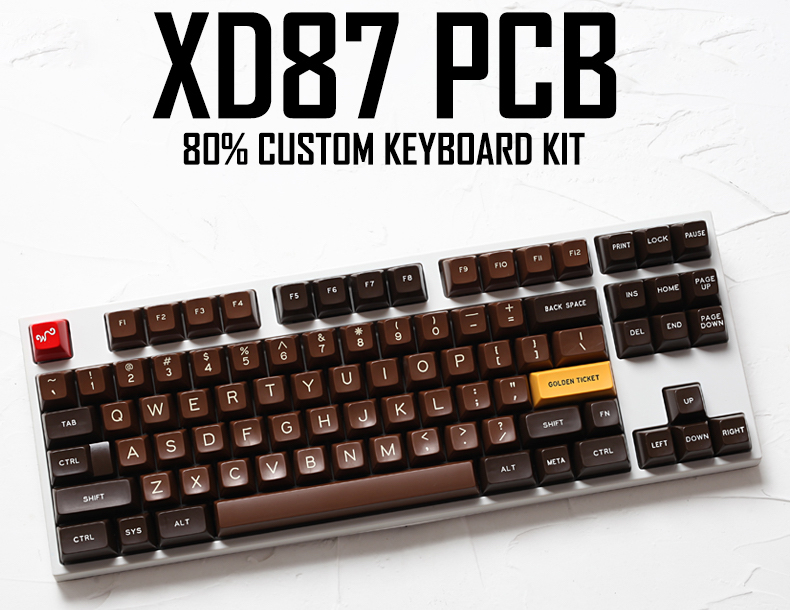
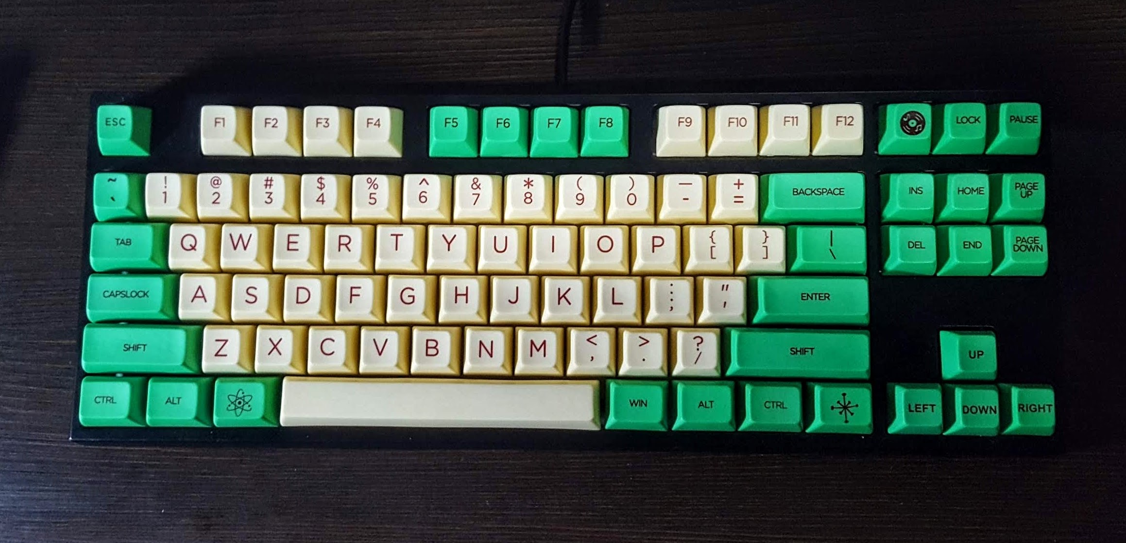
After having played a bit with CircuitPython, KMK and a 4x5 keyboard powered by this stack, the natural next step was to build a full-sized keyboard, one that can be a daily driver. I selected the KRepublic's XD87 kit as basis.
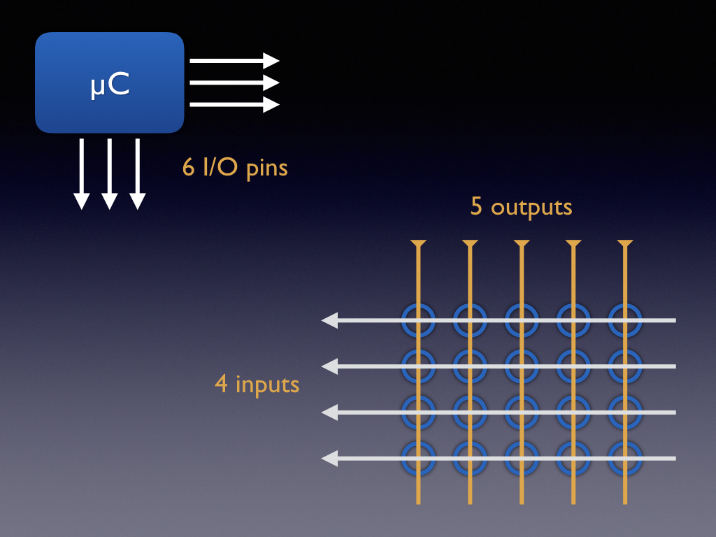
Before the PCB even arrived, one issue was the necessary number of I/O ports. The board would need 23 or 24, the ItsyBitsy M4 has only 22 or 23. Even if they were just enough, it would be nice to have some spare pins for further improvements, or in case some pin failed for whatever reason.
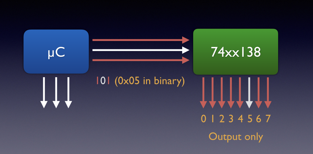
There are ways to stretch the I/O pin count. One option is to use 74xx chips e.g. the 74xx138: easy to find for 3.3V, making 8 out of every 3 I/O pins, albeit output-only.
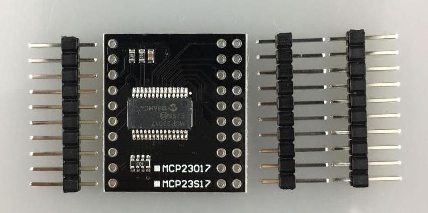
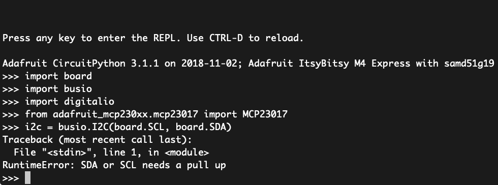
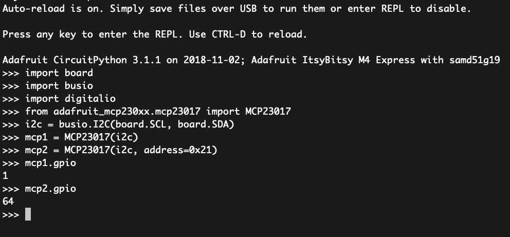
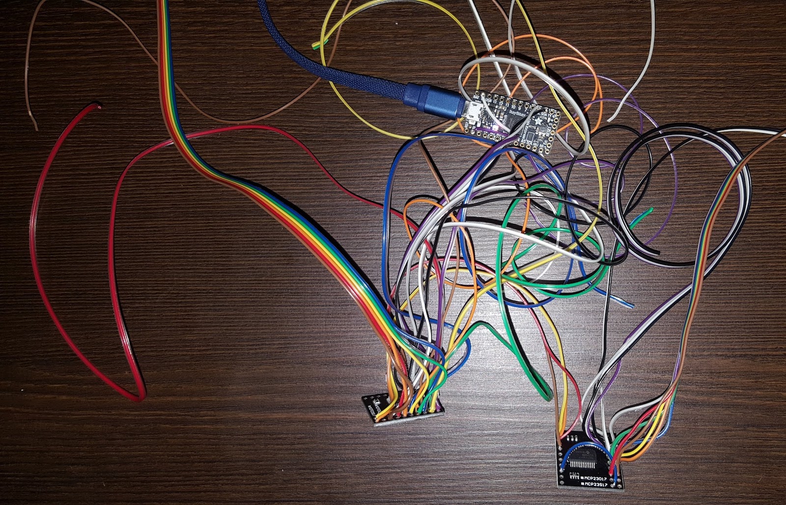
Another option, modern and popular, is an I/O expander chip like the MCP23017. The MCP is controlled via I2C or SPI. Using multiple units, we could make up to 128 I/O pins out of just two I2C controlling lines.
One question remains: is the I/O expander, controlled via I2C by an interpreted language, fast enough to scan a big keyboard? Let's sail close to the wind for a while, and leave the acid tests for the end.
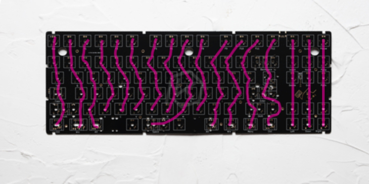
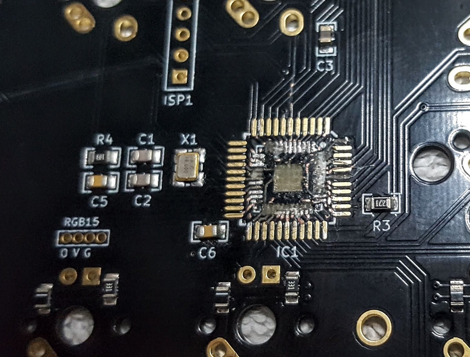
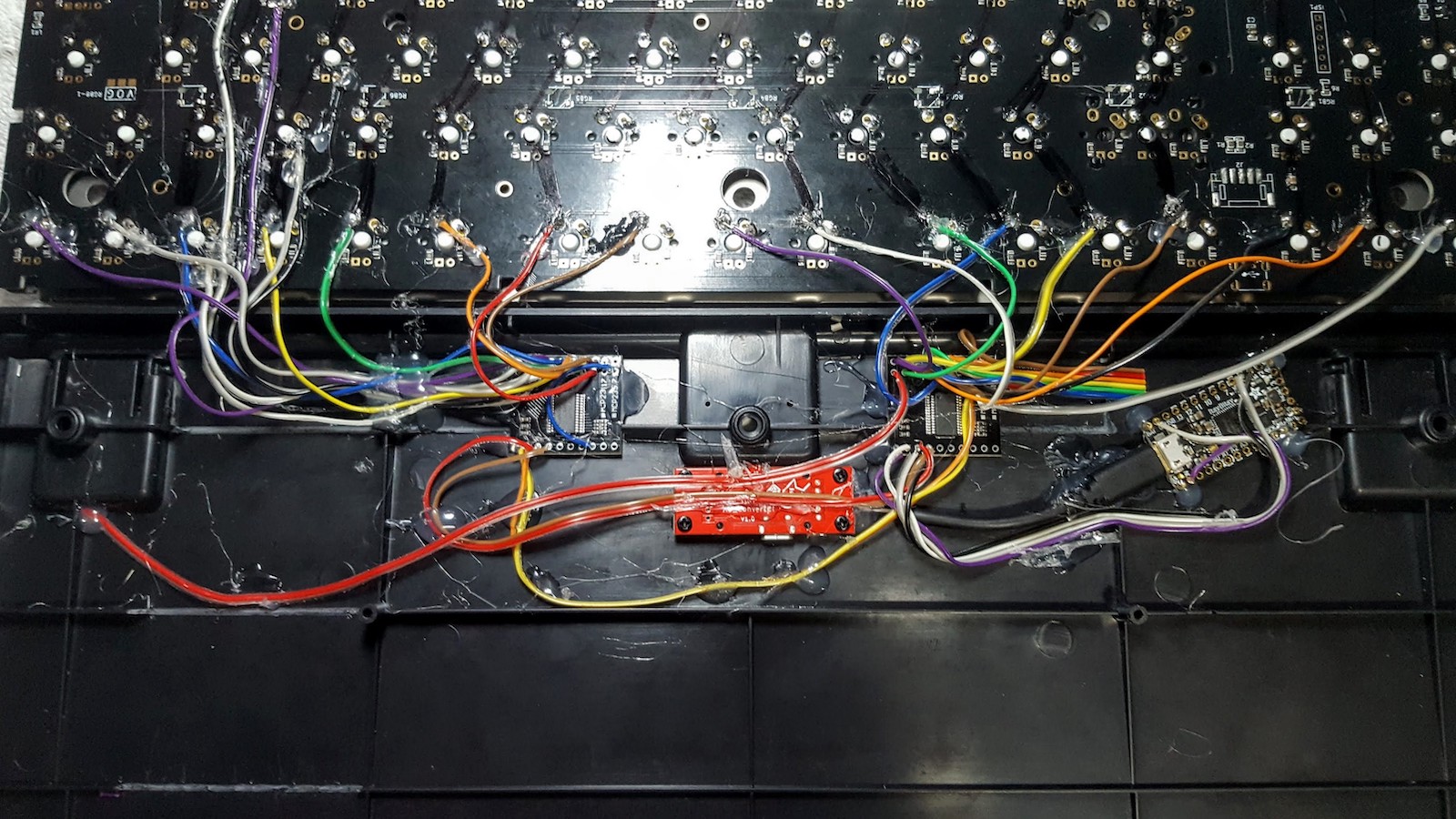
Once the components arrived, we can start assembling. First off, we need to discover how the keyboard matrix is wired in the PCB. It had one less column (17) than expected. The diodes point to rows (COL2ROW in QMK's jargon). Next step was a bit sacrilegious: "damage" the PCB, removing the 8-bit controller and backlight LEDs.
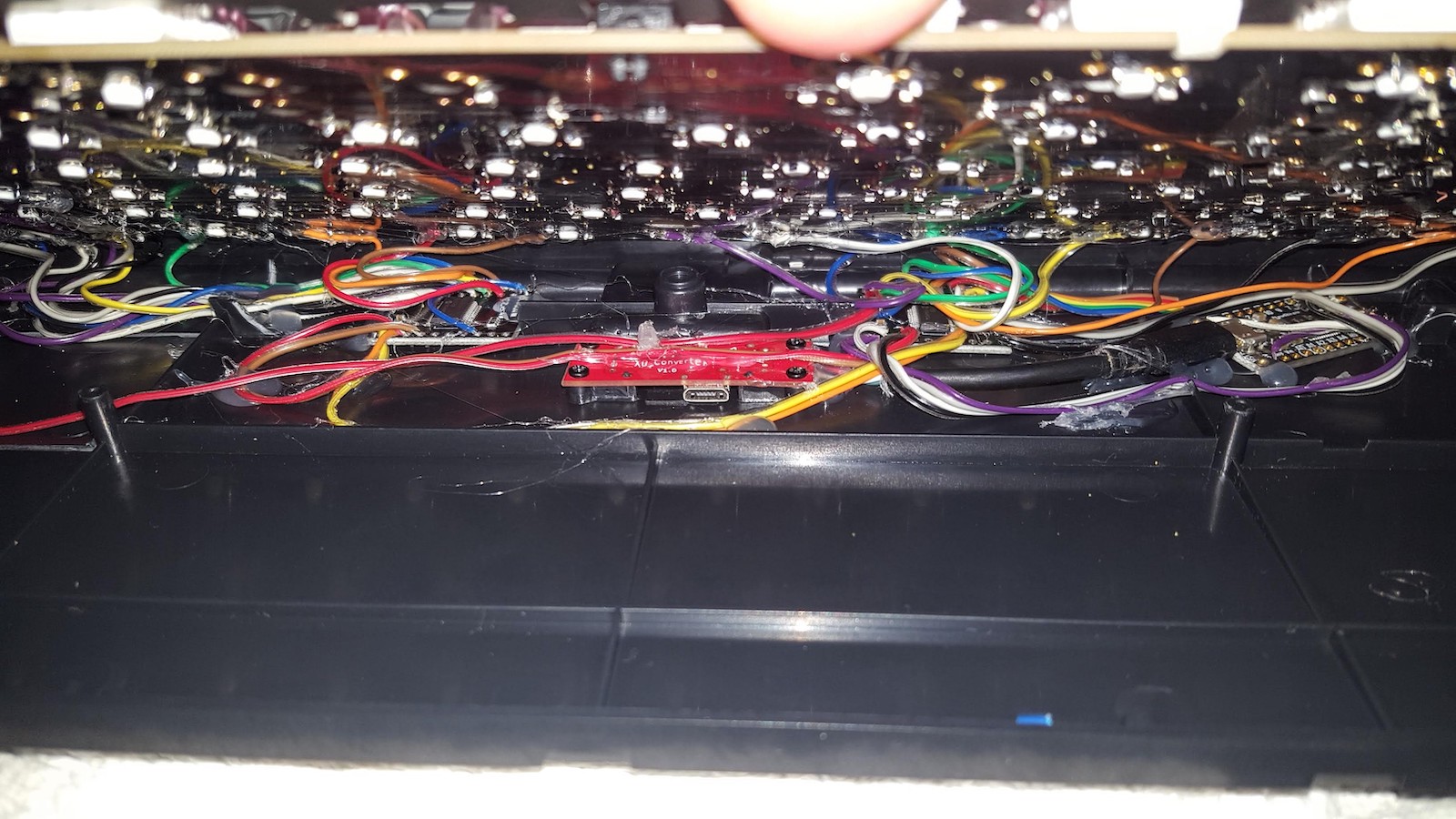
The extra circuits need to find a home within the enclosure. The back of the enclosure offers more space, and we need to take some ribs here and there for the wires. Next step was to connect the ItsyBisty to the twin MCPs.
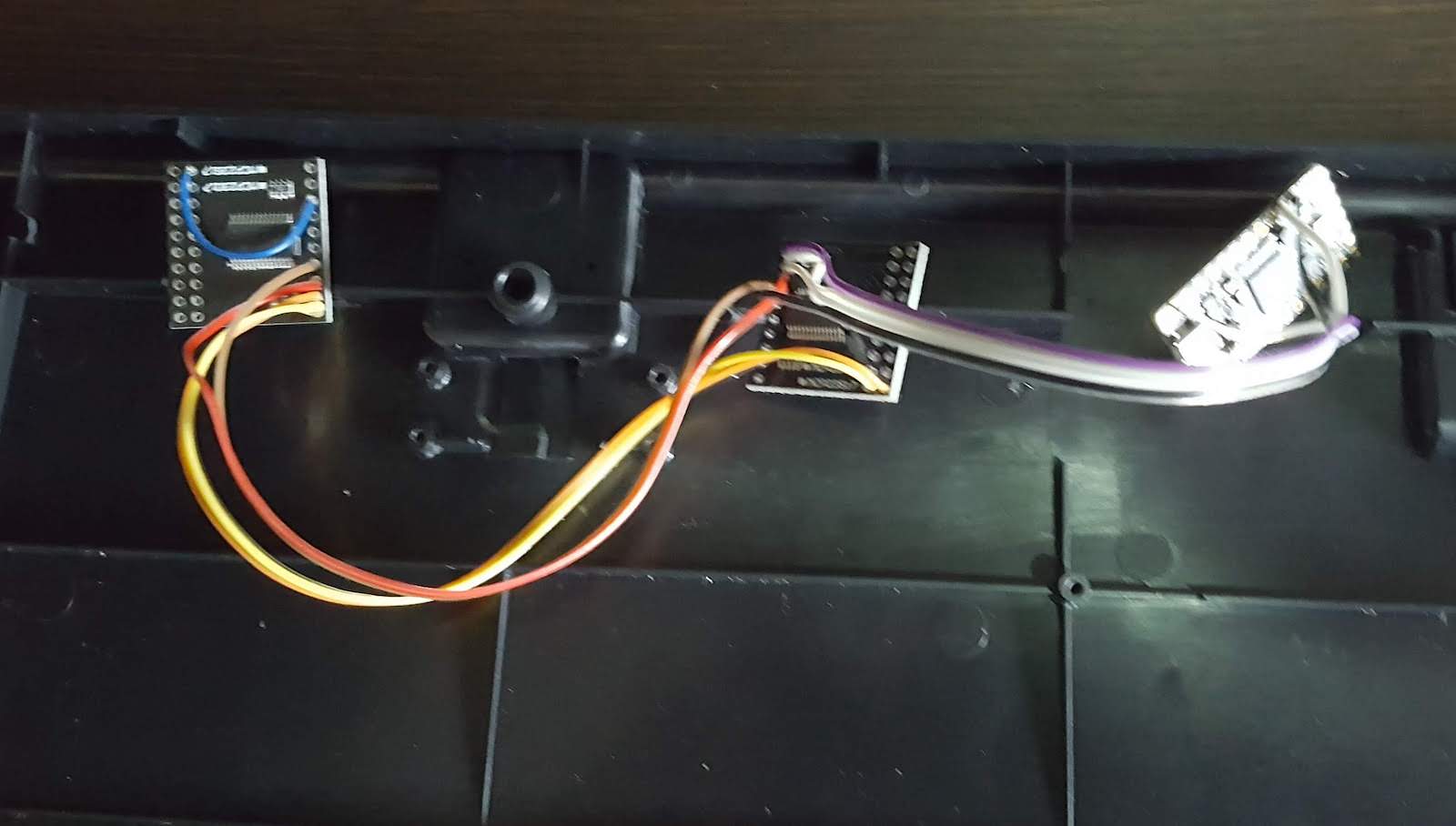
The expander boards came with pull-up resistors so we didn't need any extra components. So far, the circuit looks clean! One nice thing about I2C is the confirmed communication, so we get instant feedback about I2C health.
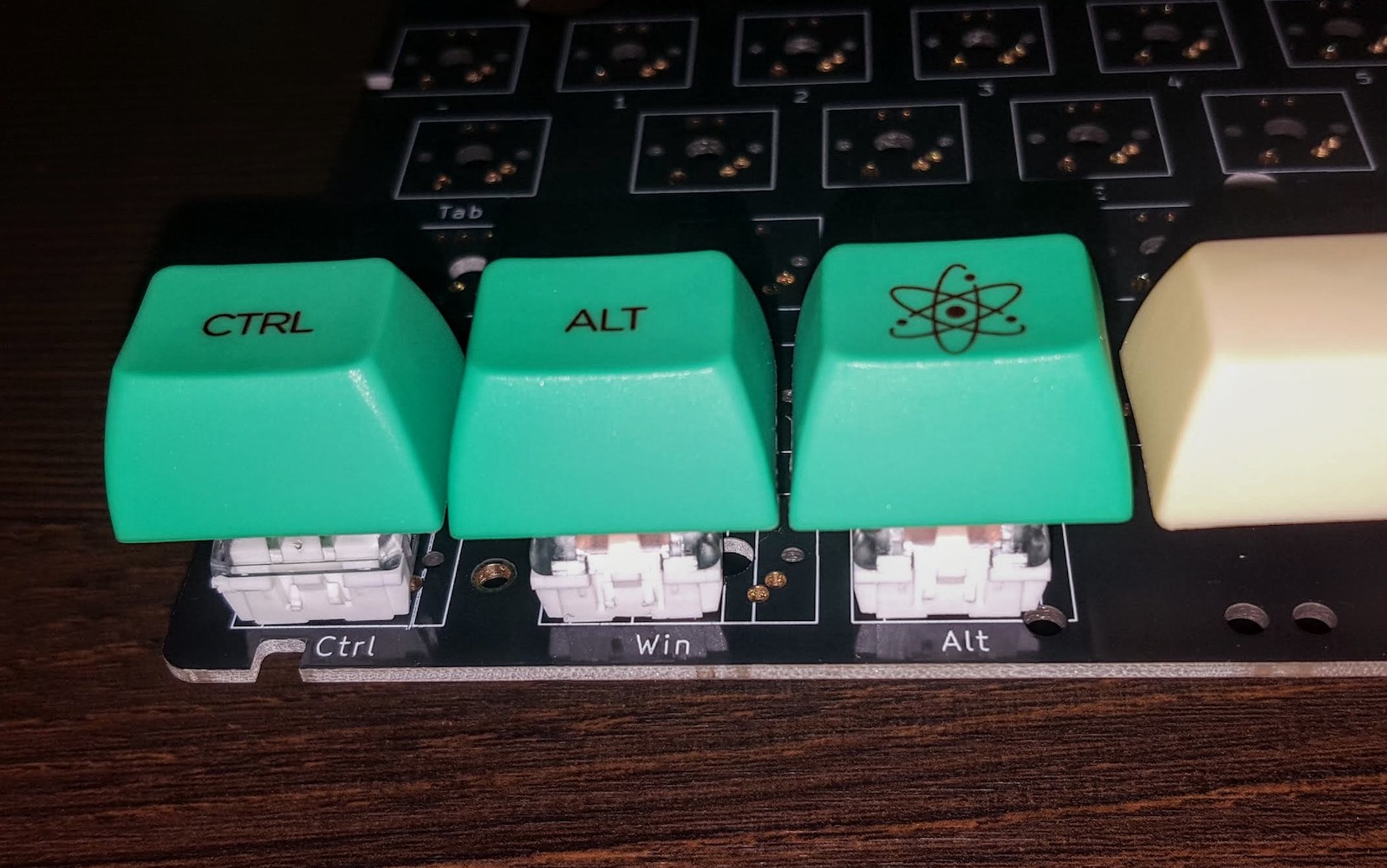
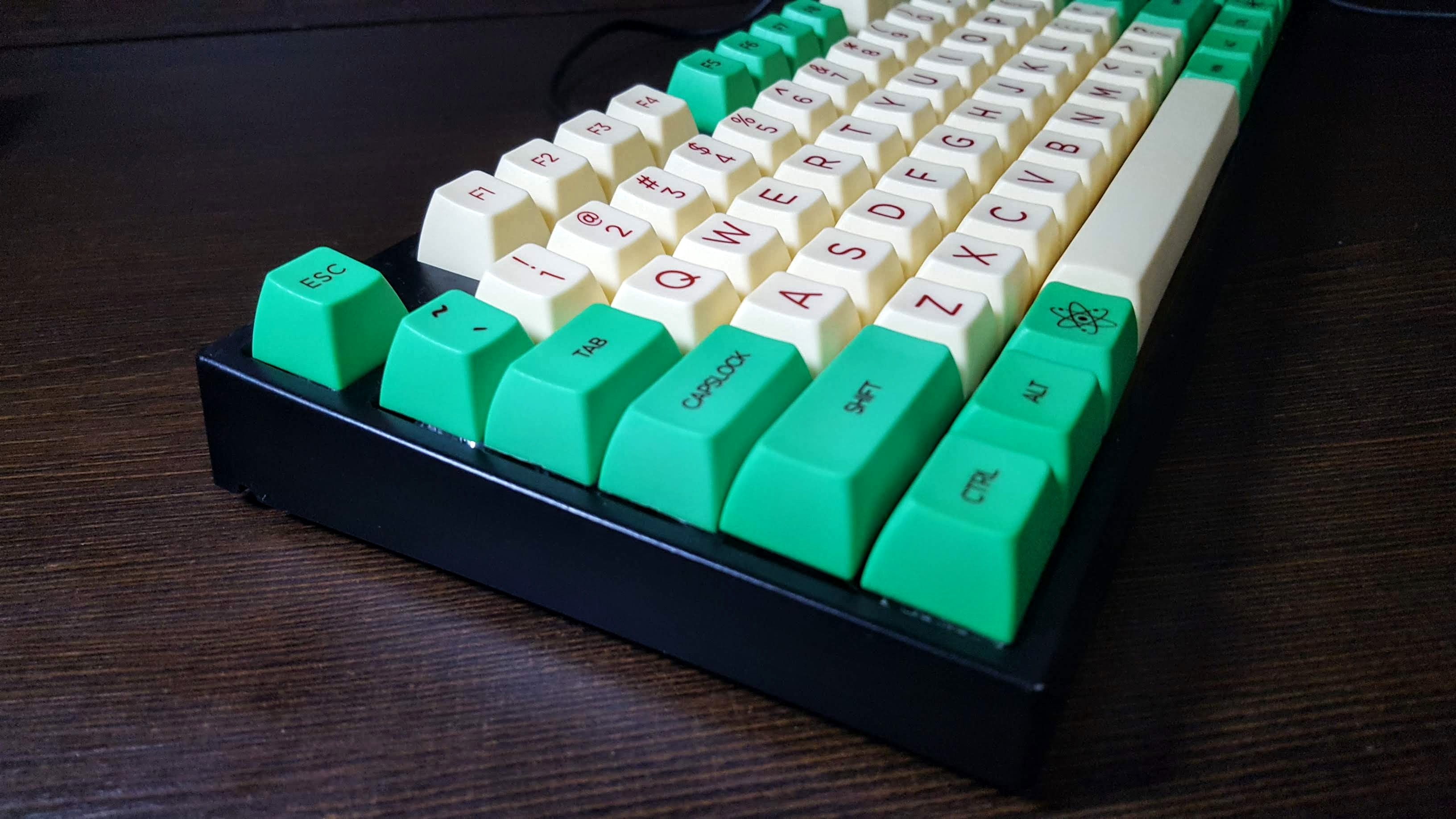
Then we proceed with mechanical assembly. I follow a sequence of steps: choose a layout among the ones allowed by the PCB, check keys' width and switch position, mount the stabilizers and check again with the keycaps. Then I solder the switches, first the corners, verify the frame is parallel with PCB, then solder the rest of the switches.
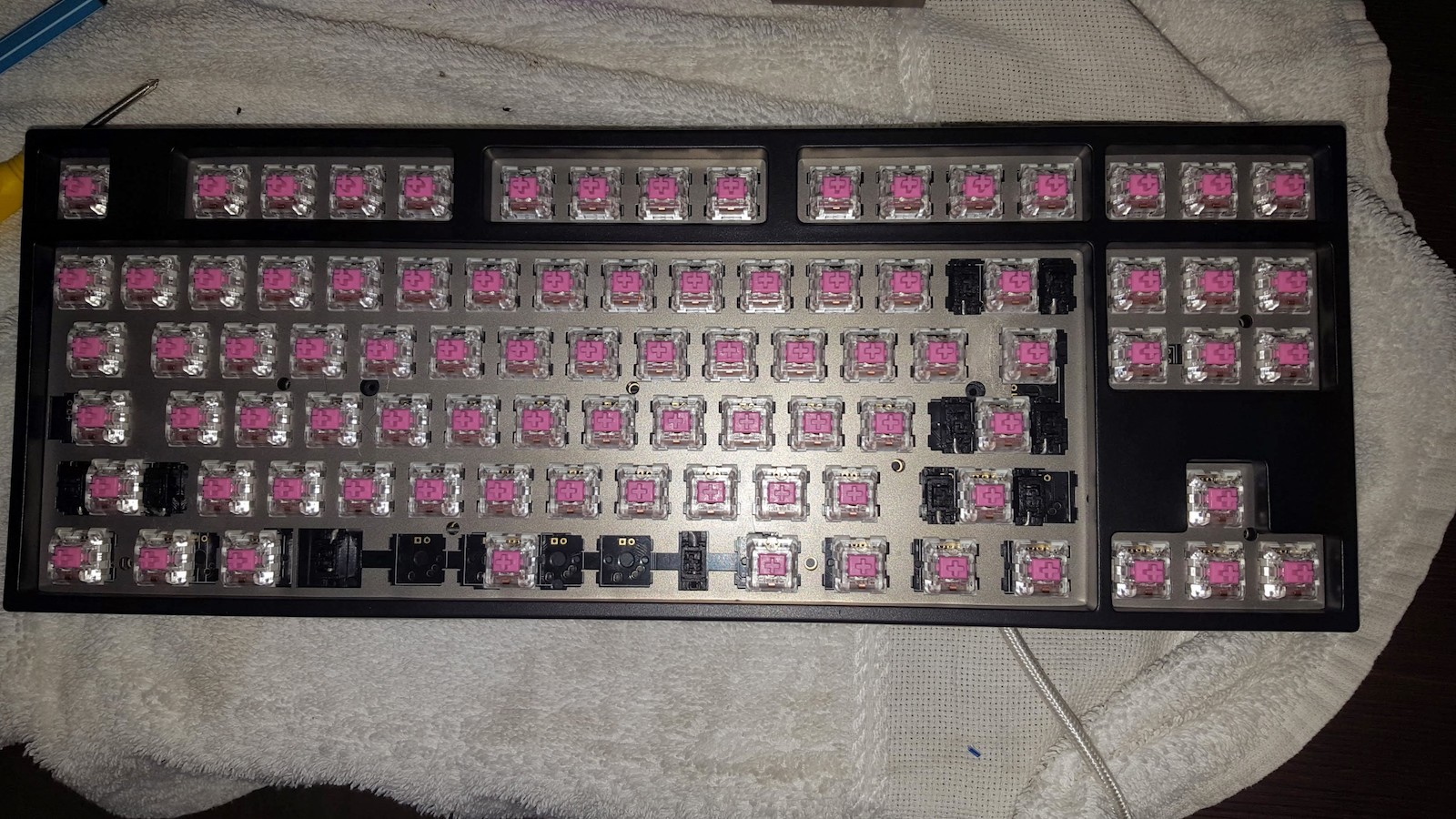
The next step is to solder wires to I/O pins, effectively patching the PCB. That was time-consuming and the sheer number of wires looked scary. In fact I just kept soldering whatever wire to whatever row or column. The relationship to I/O pins would be discovered later by software. I soldered all MCP pins to wires, even though many would go unused, just in case.
Once every row and column got a wire, I wrote a small program to probe the matrix. By pressing every key, we related the whole matrix with their I/O pins, and also verified en passant that every wire was well-soldered and every switch was working.
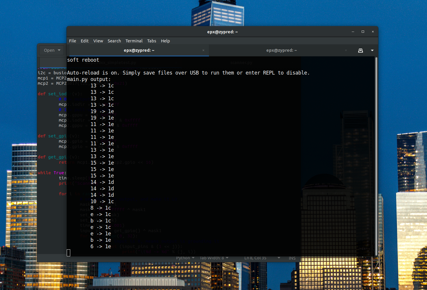
The MCP23017 has configurable internal pull-up resistors, but not pull-down. So we need to scan the matrix in "inverse" mode, by setting outputs LO one at a time, and checking which inputs have gone LO as well.
At this point, the hardware part is done. Let's talk a bit about the software. The base firmware is KMK, written in Python, augmented by a matrix scanner for the I/O expanders. The keymap itself was easy since the layout is the well-known tenkeyless.
Now we revisit the old question: will it scan (fast enough)? Subjectively the keyboard just worked well, so at first glance the I/O expander was a good choice.
By instrumenting the code I found the scan rate was 35 times a second or 35Hz. This is a bit slow; something near to 100Hz would be best. KMK was able to scan the 4x5 keyboard at 250Hz (update: 350Hz with CircuitPython 4.1) so this is sort of a hard limit; it would be pointless to aim for rates like 500 or 1000Hz.
After some optimization tweaks, the scanner reached 90Hz; I think it goes up to 100Hz without instrumentation. The optimized code is not as clear as the original, there is some bitwise magic here and there, but that's the price. (Update: with CircuitPython 4.1.0, it reaches 110Hz.)
The only wrinkle in a CircuitPython-based keyboard is not working well in boot phase: things like UEFI/BIOS settings, waking up from hybernation, or FileVault password typing in macOS. It is probably related to device enumeration: a CircuitPython board enumerates several USB virtual devices (storage, keyboard, mouse, serial) and UEFI expects keyboards to be keyboards only, or the keyboard should be the first enumeration.