 What is the Kv rating of RC model motors?
What is the Kv rating of RC model motors?
What is the Kv rating of RC model motors?
First off, I've made available a spreadsheet study for permanent magnet motors. It contains four worked examples: brushed 390 and 540, and two brushless units typically employed as upgrades of the first ones. A "bonus" tab also illustrates the series-wound motor that is not seen in RC models.
Now, this spreadsheet shows a list of Racerstar brushless motors for RC cars, that are in my personal range of interests.
The motors used on RC models are almost always DC and PM, be it brushed or brushless. The basic principle behind every motor is the reaction of the rotor's ("core") magnetic field and the stator's ("casing") field. In a PM motor, one of the fields is supplied by permanent magnets. Other kinds of motor (induction, series-wound) create both fields using electricity.
Though PMDC motors are associated with toys and low-power applications, they are no longer toyish. They are the most efficient motors since the PM's magnetic flux does not consume power. The evolution of power electronics and stronger magnets opened new fields for the PM motor, and multiple-thousand horsepower units have been built.
But the PMDC motor must be applied correctly. It must be "matched" in torque and power with the application, and it is best used when the power demand is constant. Variable-demand applications are better off with other types e.g. the Tesla cars use induction motors and railroad locomotives use either series-wound DC or induction AC.
The major characterisic of a PMDC motor is to have a definite maximum RPM, limited by Kv rating and by supplied voltage. A 3600Kv motor fed with 10V cannot go beyond 36,000RPM.
Every PMDC motor can be used as a generator. If a 3600Kv motor is spun at 36,000RPM, it will generate 10V unloaded. On the other hand, feeding it with 10V will spin it a bit less, because there are always losses (mechanical, electrical and magnetic).
This relationship is useful because the PMDC motor is self-limited in RPM (while a series-wound may destroy itself if run unloaded). Moreover, it is easy to control RPM by controlling the input voltage.
The torque of a PMDC motor is linearly proportional to the current passing through it. Unfortunately it means that heat dissipation increases quadratically with torque. (In contrast, the series-wound motor has a linear relationship between torque and heat.)
As mentioned before, the PMDC motor is also a generator. This is true even while it is functioning as a motor. In the example above, the 3600Kv motor can't go beyond 36,000RPM when fed with 10V because it is generating back electromotive force (BEMF) of 10V against the input, and the net voltage is zero.
In order to current to flow and generate torque, the BEMF must be smaller than input voltage, and therefore the RPM must be smaller than (Kv × tensão). If the example motor spins at 21,600RPM, the BEMF is 6V. If it is fed with 10V, the net voltage is 4V. For an internal resistance of 0.5 ohms, the current would be 4/0.5=8 amperes.
Joining these facts, we have that
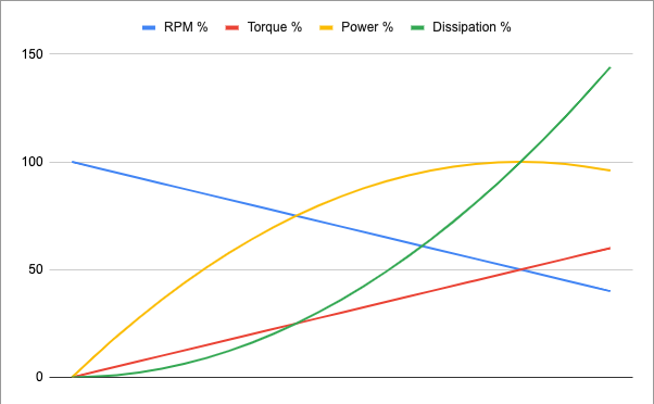
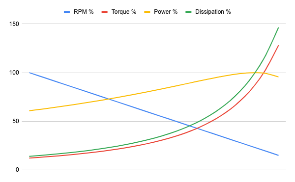
The PMDC motor offers great starting torque, which is good because it accelerates fast to the cruise RPM. But it is easy to overload such a motor, because it can still move the load in a first moment, albeit working under low efficiency and possibly being damaged by heat. The biggest horespower is at 50% of max RPM, but at this point the efficiency is also 50%. For each 100W of mechanical power, there is another 100W of heat dissipation (total energy input is 200W). In RPMs lower than 50% max, the share is even worse.
To be efficient, and to last longer, the PMDC must work light and lukewarm, with RPM near the maximum. For example, at 90% of max RPM, the motor is (in theory) 90% efficient. At this operation point, the motor generates only 1/10th of starting torque, and just 1/3 of the maximum horsepower.
By and large, the maximum power of a PMDC motor is dictated by its size, for two reasons:
That is, in the best case the motor power is a function of its volume, and in the worst case it is a function of casing area; in practice it is sandwitched in between.
The RC model brushless motors are often characterized by their Kv rating. As we saw before, the Kv rating is the relationship between input voltage and maximum RPM. Is there more in this rating?
Another seldom-seen rating is Ke, the reciprocal of Kv and adjusted for angular speed. The Kv number is more "ergonomic", it is easier to grasp a 1000 Kv motor than a 0.0096 Ke motor, even though both are equivalent.
This rating is based on back electromotive force (BEMF). When an electrical conductor (wire or coil) is inside a variable magnetic field, a BEMF is inducted on this conductor. The BEMF is proportional to the number of turns of the coil, and to the strength of the magnetic field.
For a PMDC motor, be it brushed or brushless, the magnetic field is supplied by permanent magnets alone. The more turns in coils and/or the stronger the magnet, the bigger the BEMF and lower the Kv rating. Using a magnet twice as strong and triple the turns would divide Kv by six.
Now the one million dolar question: is Kv related to torque? Yes! Even though many sources say that no, the torque of a motor is inversely proportional to Kv. A 1000Kv motor has twice the torque of a 2000Kv motor given the same electric current.
It does not mean that the first motor is "better"; it only means that horsepower is shared differently between torque and RPM. If we installed 2:1 reduction gears inside a 2000Kv motor, it would look as a 1000Kv from outside. A reduction does not make a motor inherently better (but it can adapt it better for a given use case).
Every PMDC motor has also a Kt rating that shows the relationship between torque and current. For example, a 0.05 Kt motor generates a torque of 0.15N.m for a current of 3A. In model RC the torque is commonly expressed as N.cm or g.cm, so 0.15N.m would be 15N.cm or 1500g.cm.
Kt is inversely proportional to Kv:
Kt =   60
     -------
      2π.Kv
Kv, Ke and Kt are actually the same thing, expressed under different units. The constants 2π and 60 adapt RPM to SI units. A 3600Kv motor (a common rating in RC car models) has a torque of 26.5g.cm per ampere. For a 30A current, the torque would be around 800 g.cm.
The Kt rating is not as often seen as Kv, because motors are typically fed with constant voltage, not constant current. If voltage is constant, current varies a lot and depends on RPM and internal resistance. Moreover, the Kt rating does not tell us the heat dissipation that a given torque will cost us (this is told by the Km rating, that we will see later).
Brushed motors have a limit around 20,000RPM, and brushless motors can go up to 50,000RPM. If the load might allow the motor to spin faster than that, the Kv rating must be chosen accordingly to input voltage to limit the RPM.
For example, a 4500Kv motor is good for 12V, while a 1200Kv motor could be fed with 40V without redlining, though other factors (current, dissipation) may further limit their performance.
Besides the mechanical limit, the magnetic and mechanical efficiencies must also be considered. The faster a motor spins, the bigger are the non-electric losses. Accordingly to this article, a brushless motor should spin no faster than 60,000RPM divided by number of poles to stay in efficient range. The article's author is more acquainted with outrunner motors; in a comment, he estimates that the base for inrunner motors is around 100,000RPM, which means 25,000RPM for 4 poles.
The ultimate gauge of the "quality" of a motor is the weight of copper windings. (I am ignoring silver- or aluminum-wound motors here.) Given a certain quantity of metal, motors with very different Kv ratings can be made, but their "quality" is roughly the same.
Suppose a 3600Kv motor that should be converted to 1800Kv. To achieve this, we need to "stretch" the wire to make coils with twice the number of turns. By doing this, the wire becomes twice as thinner, so the internal resistance is increased fourfold.
With 4x the resistance, current is reduced by a factor of 4, as well as the torque. But, since the specific torque (Kt) increased by a factor of 2 (since it is inverse to Kv) the motor's torque is cut only by half. The maximum RPM is also cut by half, so the horsepower is 1/4th of the original.
Up to now, it seems that the new motor with smaller Kv is "worse", but there is a simple solution: just double the input voltage. It doubles the torque, the RPM and the motor goes back to the original horsepower.
From this point of view, the Kv rating goes hand to hand with input voltage. Choosing the Kv is simply a method to adapt the motor to the available input voltage.
If I can't replace the battery, a higher-Kv motor will indeed yield higher torque and higher horsepower, since the internal resistance is smaller, given the same copper in windings. Perhaps because of this, many modelers think higher Kv = higher horsepower. But this is a terrible way to increase horsepower, because the motor will also demand a huge current and dissipate a lot of heat.
One remedy is to match a kigher Kv motor with a smaller pinion. By increasing the reduction, the motor can reach nigher RPMs, delivering higher horsepower mainly by spinning faster instead of increasing torque.
As said before, the Kv rating is not enough to fully describe a motor. We also need to know its internal resistance. Or to know the Km rating, also know as "Motor size constant". It condenses the relationship between torque and efficiency:
Km =        torque
     -------------------------
      sqroot(dissipated power)
A perfect motor would generate torque with no dissipation, and would have an infinite Km. By some manipulation, we can find the relationship between Km, Kv and internal resistance: podemos determinar a proporção de Km em relação a Kv e resistência interna:
Km =            60
       ----------------------------------------
        6.28 . Kv . sqroot(internal resistance)
The formula above says that, from the point of view of Km rating, a motor with high Kv is "worse" because it needs more current to generate the same torque. But it does not mean that a higher Kv is really bad — Km only considers torque, not the horsepower.
There is an important relationship between Km and the quantity of copper in windings. If we modify the motor's Kv but keep the copper weight constant, the Km rating does not change. Reusing the thought experiment we did before: if Kv is halved, resistance increases by a factor of 4, but one thing perfectly balances the other in the Km formula.
The Km rating tends to be higher for motors physically larger. This can be shown by another thought experiment. Suppose we get two exactly equal PMDC motors, connect them electrically in parallel, and coupled shafts. The Kv of the whole machine is the same, but internal resistance is halved, which improves the Km rating by 41%. If we connect the same two motors in series, the internal resistance is doubled but then Kv is halved, improving the Km by the same amount (41%).
Keeping all other parameters constant, the Kv rating is inversely proportional to the number of turns in coil.
Before the brushless motors, the custom in RC modeling was to label motors by the number of turns, because everybody used the same type of motor: 540 brushed. The vanilla RS-540 has 27 turns. Motors with more turns (not very common) are used in high-torque applications, while less turns are considered "hotter". The latter tend to be better built as well, because they really heat up.
The folks from slot car community use the 130 motor and also labels motors by the turn count. The standard is 13 turns, but racing motors may have 6 or even 4. It was a common home-made modification back in the time, get the slot car that came in the Christmas gift and remove some turns to make it faster.
The metric of turns was practical for brushed motors because the biggest contributor to the internal resistance — the brush/commutator mechanism — is always there, and the basic construction doesn't change much from one model to the next. On the other hand, in brushless motors the sole source of internal resistance is the coil wire itself, and there is more constructive freedom (there are inrunner and outrunner motors, etc.).
It is opportune to clarify some differences between brushed and brushless motors.
Every motor needs some sort of switching mechanism, internal or external to it, so the magnetic field rotates. In the case of PMDC motors, the field must be in sync with the angular shaft position. (The latter requisite is waived in induction and stepper motors.)
In a brushed motor, the commutator is indeed mechanical and embedded into the motor. The biggest advantage is simplicity: just feed the motor and it spins. The brushes are a maintenance problem, but a good-quality motor that is not overloaded can last years. Other disvantages are the big electrical resistance and the big friction losses.
The brushed motor has coils in the rotor, so they need to withstand the centrifugal force, which may limit the maximum RPM. The heat generated by the coils (and by the commutator) is difficult to remove, often needing forced cooling which is another mechanical loss.
The coreless motor is also a brushed motor, but the rotor lacks a metallic armature. The coil supports itself and transmit torque to the shaft. This allows for a lighter, smaller motor that accelerates very rapidly. But it must not be overloaded, since there is no metal armature to absorb any excess heat.
The brushless motor has stationary coils, so the generated heat can be easily removed through the external case. There are no friction or electrical resistance from brushes. The only true disvantage is needing an external electronic controller.
The brushless controller/ESC just be "matched" with the controlled motor, particulary in the case of "sensorless" motors, the most common these days. Only three leads connect controller and motor, and the shaft position is inferred by the BEMF. Since the BEMF is related to Kv, each controller will not work for motors ouside a certain Kv range. Besides, there must be voltage and current compatibility.
The "sensored" brushless motors have Hall sensors to detect the shaft angular position. They are less and less common but still exist. In their case, there is an additional 6-wire cable connecting motor and controller for position detection. The controller does not need to be so closely matched with a Kv range, and may be simpler. Because of this, some still characterize sensored motors by the number of turns, instead of Kv rating.
There is some discussion about the nature of brushless PMDC motors, also known as BLDC. Some say it is actually an AC synchronous motor. Indeed they look similar, and get even more similar when the synchronous motor has permanent magnets in rotor instead of a DC coil. Such a motor is known as PMSM (permanent magnet synchronous motor).
Both synchronous and BLDC motors have three main power leads. But the BLDC controller feeds only two at a time, perhaps it does a smooth ("trapezoidal") transition between the current pair and the next. The synchonous motor is fed with 3-phase sinusoidal AC.
The PMSM motor is more efficient and vibrates less, since its torque is constant. On the other hand, a PMSM controller is more complext and may be less eficient. A BLDC controller may use the unfed cable to detect rotor position in sensorless mode, while the PMSM controller absolutely needs a shaft position sensor.
The internal construction of BLDC and PMSM motors may be different in order to achieve maximum efficiency with the repective controller.
BLDC, PMSM, induction, etc. motors tend to have three coil groups, which means six power leads. But only three emerge from the motor; the coils are internally connected in Y (wye/star) or in Δ (delta, triangle). The same happens with brushed motors: in a 3-pole motor, the commutator has only three segments instead of six, and the rotor coils are interconnected to close the circuit.
In either connection, it is impossible to feed only one coil at a time. By feeding two leads, the current flows through at least two coils, and sometimes through all the three.
A Y-connected motor has higher impedance, higher internal resistance, higher torque and lower Kv rating, always by a factor of 1.73 in relation to the Δ connection. An inherent disvantage of Δ-connected BLDC is the current circulation within the delta that wastes energy; the Y connection is more usual for them. In 3-phase AC motors, both are equally good and the same motor can use either one, be it to adapt to different line voltages, be it in a star-delta startup sequence.
If a BLDC motor exposes the six power leads, it is possible for a controller to "shift gears", connecting the motor in Y or Δ as most convenient. A 2:1 gearbox without any gears whatsoever is a tempting proposal. There are a handful of DIY projects that have used this trick on RC models and electric scooters.