 QAM modem: TX part
QAM modem: TX part
QAM modem: TX part
If you are an old-timer computer guy like me... you are probably nostalgic of this noise:
After playing with analog modulations, this time I wanted to play with some digital modulation. I thought about PSK and FSK, but they are quite simple, and are just particular cases of QAM — Quadrature Amplitude Modulation. The audio abovementioned was generated by my "modem", written in Python.
Writing the transmission (TX) part of a modem is easy. The big challenge is to write the reception (RX) part. As you will see, the RX code is far longer and more complicated.
I did not try to write the perfect modem, so this thing will probably not work over a ham radio link or any other non-ideal transmission medium. I will point out the shortcomings that I know of, and there are for sure a whole bunch of other problems that I don't even know of. It's just to have fun, after all.
UPDATE: People have asked me for references. My reference was an excellent, precious Brazilian book called "Modem e Transmissão de Dados", by Fabio Montoro. It is out of print and written in Portuguese. I can't name a English good reference, but I guess that any book about telecommunication basics should cover the basic concepts like carriers, modulation, etc.
QAM modulation takes a carrier of fixed frequency and changes phase as well as amplitude, accordingly to the bits that are to be sent. The output wave is something like this:
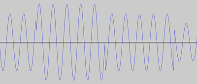
Note that QAM, like AM, never changes carrier frequency. It would not be possible to change frequency along with phase and amplitude, because the changes would smear each other. (The digital cousin of FM is FSK).
Each change in QAM signal may carry several bits. For example, if we establish that we have 4 possible phases (0, 90, 180 and 270 degrees), and 2 possible amplitudes (50% and 100%), we have 8 possible combinations, which allow us to send 3 bits per sample (log2 8).
So we have this concept of "baud rate", which is the number of symbol changes per second. The data bit rate is the baud rate multiplied by the number of bits that each symbol can carry.
Of course, we need to establish a relationship between phases, amplitudes and transmitted bits in an orderly manner. The nost common way to do it is using a "constellation" graph like this:
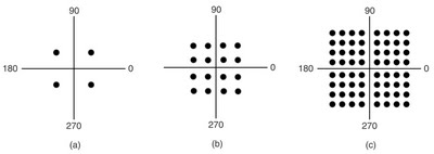
In the image above, we have 3 constellations. At left, a very simple one, with only four points. If you draw a line from origin (coordinates 0,0) to a given point, the line length is the signal amplitude, and line angle is the phase change. We just need to attribute a different bit pattern for each point.
Since all four points of the leftmost constellation are equidistant from origin, we can say that this constellation is not really QAM; it is PSK (phase shift keying) because it only uses phase changes to send information The other constellations are more cluttered, and have points of several amplitudes.
Without further delay, here is the code of modem TX part:
#!/usr/bin/env python

import wave, struct, math

SAMPLE_RATE = 44100.0 # Hz
CARRIER = 1800.0 # Hz
BAUD_RATE = 360.0 # Hz
PHASES = 8
AMPLITUDES = 4
BITS_PER_SYMBOL = 5

# generate constellation of phases and amplitudes
# for each possible symbol, and attribute it to a
# certain bit pattern. I avoided deliberately the
# complex numbers, even though they make things
# easier when dealing with constellations.
#
# Make sure that all ones = maximum aplitude and 0 phase
constellation = {}
for p in range(0, PHASES):
    for a in range(0, AMPLITUDES):
        s = p * AMPLITUDES + a
        constellation[s] = (PHASES - p - 1, a + 1)

# This is the message we want to send
msg = "Abracadabra!"
# msg = open("modem_tx.py").read()

# Convert message to a list of bits, adding start/stop bits
msgbits = []
for byte in msg:
    byte = ord(byte)
    msgbits.append(0) # start bit
    for bit in range(7, -1, -1): # MSB
        msgbits.append((byte >> bit) % 2)
    msgbits.append(1) # stop bit

# Round bit stream to BITS_PER_SYMBOL
while len(msgbits) % BITS_PER_SYMBOL:
    msgbits.append(0)

# Group bit stream into symbols
msgsymbols = []
for n in range(0, len(msgbits), BITS_PER_SYMBOL):
    symbol = 0
    for bit in range(0, BITS_PER_SYMBOL):
        symbol += msgbits[n + bit] << (BITS_PER_SYMBOL - bit - 1)
    msgsymbols.append(symbol)

# Add 1 second worth of all-1 bits in header, plus a trailer.
# The 11111 bit pattern generates a pure carrier, that receiver
# can recognize and train.
allones = (1 << BITS_PER_SYMBOL) - 1
train_sequence = [ allones for x in range(0, int(BAUD_RATE)) ]
finish_sequence = [ allones, allones ]
msgsymbols = train_sequence + msgsymbols + finish_sequence

qam = wave.open("qam.wav", "w")
qam.setnchannels(1)
qam.setsampwidth(2)
qam.setframerate(44100)

t = -1
phase_int = 0
samples = []
for symbol in msgsymbols:
    amplitude = 0.9 * constellation[symbol][1] / AMPLITUDES
    # Phase change is integrated so we don't need absolute phase
    # at receiver side.
    phase_int += constellation[symbol][0]
    phase_int %= PHASES
    phase = phase_int / (0.0 + PHASES)

    # It would be easier to manipulate phase using complex numbers,
    # but I thought this way would be clearer.

    # Play the carrier at chosen phase/amplitude for 1/BAUD_RATE secs
    for baud_length in range(0, int(SAMPLE_RATE / BAUD_RATE)):
        t += 1
        sample = math.cos(CARRIER * t * math.pi * 2 / SAMPLE_RATE \
                          + 2 * math.pi * phase)
        sample *= amplitude
        samples.append(int(sample * 32767))

qam.writeframes(struct.pack('%dh' % len(samples), *samples))

print "%d symbols sent" % len(msgsymbols)
Actually, the most complicated part of TX is the bit stream expansion. The original message is supplied as a string of bytes, so we need to "explode" it to individual bits, and add start and stop bits. The output signal itself is easy to generate, courtesy of math.cos() function :)
Do you remember that modems used to "whistle" for a couple seconds before connection? It was necessary to do the same here, so the receiver can get "trained" to the signal. Despite the fact the thing reads data from a high-quality sound file, the training phase is still needed.
I employed a 1800 Hz carrier just out of nostalgy, because this resembles the pitch of once-ubiguitous telephone modems.
The other parameters were found empirically; they are just below the level in which RX code fails to recover the message.
The constellation I generate would plot like a bicycle wheel, with "spokes" coming from origin to the outer rim. This is not an optimal constellation because it is more cluttered near the origin, which means that those low-amplitude symbols are more easily misinterpreted in presence of noise. The constellations shown in the second picture have equidistant points.
There is another reason why my constellation is sub-optimal. I opted not to use complex numbers, to keep the code more readable for non-mathematically-inclined programmers.
Unfortunately, making an optimal constellation without complex numbers means unreadable code too, so I chose to keep it simple and sub-optimal. (I plan to write a version of this QAM code using complex numbers in a future post.)
Yet another potential problem of my constellation, is that there are 0-degree points, meaning a symbol that does not change phase. This is difficult on RX because if such a symbol is sent repeatedly, the QAM signal will not have any "bump" between symbols, and RX will have to guess the symbol size. Another thing to fix in a new modem version.
Talking about phase, the phase change is integrated at TX side. For example, if you have several 90-degree symbols in sequence, the angles are accumulated, so the output signal will have 90, 180, 270, 0, 90, 180... phased symbols.
At RX side, the phase change is taken into account, so the symbols are correctly interpreted as 90, 90, 90, 90... If phase were not integrated at TX, the RX side would have to know the absolute phase all the time, and would lose forever the sync as soon as the first noise struck the signal.
Note that amplitude, by its nature, does not need to be integrated to be correctly interpreted by RX. A simple moving average at RX side is enough to know the amplitude range.
The bit stream can also be conditioned by a "randomizer". It avoids long sequences of 0s and 1s, thus avoiding long sequences of a single symbol, and making RX life easier. I did not implement a randomizer in this version, but perhaps I'll do in the next one.