 Baseband digital modulation, introduction
Baseband digital modulation, introduction
Baseband digital modulation, introduction
Baseband digital modulation encodes a stream of bits into a dedicated channel, allowing successful transmission of data.
It is called 'baseband' because it is allowed to use the full bandwidth of the channel. And it is called 'digital' because the message to be transmitted is of discrete nature (normally, a stream of bits).
Baseband modulation techniques are also called line codes.
For example, each Ethernet connection has a dedicated Ethernet cable, so it can be modulated as baseband. Radio, TV, cell phones must use modulations like AM, FM or QAM, since they share the air medium with many other transmitters, and each one must fit in a thin slice of the bandwidth.
In some cases, the baseband digital modulation is just an intermediate step; its result is fed into a conventional modulator. This technique allows for a very simple analog stage, and it works as long as the analog bandwidth is enough to fit the digital signal.
This text is a general introduction to the challenges that a modulator must overcome to send a digital message from point A to point B with success.
A stream of bits is deceptively simple. Let's see how a naïve transmitter (TX) would send the letter 'C' over a channel:
| 0 | 1 | 0 | 0 | 0 | 0 | 1 | 1 |
The red color is the signal level. It is "high" for 1 and "low" for 0, for whatever definitions of "high level" and "low level". For example, in computer circuits, "high" is 5 volts and "low" is 0 volts. It could be any other pair of voltages.
The above format is named NRZ (Non-Return to Zero), because the signal stays high between two bits 1. On the other hand, a "return to zero" signal would show an on-off pattern for every bit 1.
The NRZ stream is easy to transmit but very difficult to interpret once received. The receiver will see this:
In order to decode this message, the receiver (RX) has to discover a number of things about the signal above:
The bit rate can be agreed upon in advance, so in theory TX and RX operate under the same bit rate and there is no need to find it out. But... clocks are not 100% precise, so there will be drift and RX must compensate for that, even if TX rate is known in advance.
The boundaries of each bit, that is, the phase of the signal, s difficult to find in any case, and even more difficult in face of noise and "rounded" square waves due to limited bandwidth.
And finally, how to know if the TX is actually transmitting? A long sequence of 0s can be a message, or perhaps TX was just turned off. In a sense, data bits can assume three states (1, 0 and "nil") but RX cannot distinguish "0" from "nil".
Worse yet, in some technologies the RX gets random data when TX is off. In such cases, RX cannot rely on a long sequence of 0s (or 1s) to detect TX silence.
The image below is a real example of reception in 433MHz, OOK modulation (technology often used in keyfob-controller devices, garage gates, etc.)
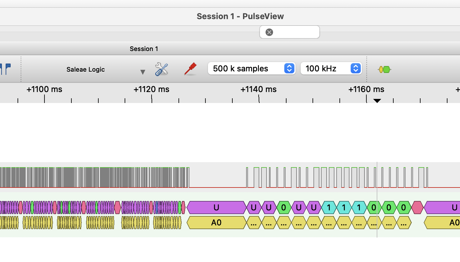
In the example above, how can we discriminate between a legit signal (right side) from noise (left side), if both are just binary sequences? How can we guarantee that a seemingly legit sequence will eventually emerge from the random noise?
These questions are all interwoven. Clock recovery is the underlying problem. A very simple solution, indeed employed by some protocols, is sending a clock signal in parallel with the message. Decodification becomes trivial, as well as determining whether TX is active or not.
| 0 | 1 | 1 | 1 | 1 | 1 | 1 | 1 | 1 | 0 |
But this is very inefficient, because now we need two channels. And receiving the clock signal itself is subject to the same problems mentioned before. For example, a long sequence of zeros in the clock channel means what? Is TX slow, or is TX off?
Sending clock on a secondary channel only works when that channel is so good that we can ignore all potential problems (bandwidth limitations, random noise, etc.). It works within a computer board, or in I2C connections (well-known by Arduino practitioners) whose wires are short.
From now on, we will assume that there is no secondary channel for the clock signal; we need to recover clock and data from a single channel.
Once upon a time, RS-232 serial ports were very popular. Nowadays, almost all serial communication flows over USB or Bluetooth connections. RS-232 asynchronous mode, also called start-stop mode, adds start and stop bits to every byte.
| 1 | 1 | 0 | 0 | 1 | 0 | 0 | 0 | 0 | 1 | 1 | 1 | 1 |
Each byte is preceded by a start bit (always 0) and followed by one or two stop bits (always 1's). Data rate is agreed upon in advance. Clock is resynchronized on each start bit, and clock drift must be small enough not to lose sync until the end of each byte.
An idle line is always positive voltage, perceived by RX as a long sequence of 1s. The start bit is always zero, and signals that TX is active. Even when bytes are sent back-to-back, the stop bit(s) guarantee that the next start bit is distinguishable, and RX local clock is reset for every byte.
RS-232 is very simple; it does not tolerate noise and needs a lot of bandwidth in proportion to data rate. In practice, this means that RS-232 cables must be of good quality and cannot be more than a few meters long, and still the reliable data rate is low. Anything beyond 112500bps was adventurous.
Start-stop code has a long history, since Telex and Baudot teleprinters, that implemented digital communication using eletromechanical and clockwork components.
Asynchronous or start-stop code does work, but it wastes bandwidth with start and stop bits for every byte. Synchronous codes, that nowadays are the rule, send long streams of bits without extra stuffing. It is the responsability of some higher-level layer to find byte boundaries.
One difficulty with synchronous codes is the lack of "clock sync" hint, like the start bit in RS-232. More sophisticated methods must take place to sync the clock and keep it in sync.
Many technologies send a long preamble, that is analog to the start bit. For example, wired Ethernet sends a 7-byte preamble before the 1500-byte packet. The preamble has a distinctive pattern like 10101010101010... that is useful to calibrate the clock, and to warn RX of an incoming packet.
Ethernet relies on the preamble and good line codes to keep the clock in sync until the end of each packet. If it was properly received, it is trivial to break the packet stream into bytes.
Manchester encoding is perhaps the simplest digital baseband encoding available. It is employed in 10-megabit wired Ethernet. It mixes clock and data to build the encoded message.
| 0 | 1 | 0 | 0 | 0 | 0 | 1 | 1 |
| 1 | 0 | 1 | 0 | 1 | 0 | 1 | 0 | 1 | 0 | 1 | 0 | 1 | 0 | 1 | 0 |
| 1 | 0 | 0 | 1 | 1 | 0 | 1 | 0 | 1 | 0 | 1 | 0 | 0 | 1 | 0 | 1 |
The result is a signal made of "chirps", not bits. Chirp rate in Manchester is twice the data rate.
Manchester decoding relies on the fact there will always be a 0-1 or 1-0 chirp transition within a bit, while neighbouring chirps of different bits have a 50% probability of being equal. This is enough to recover the clock after analyzing a number of chirps.
The bit rate must be more or less agreed in advance, but there is room to accomodate a fair variation, in particular if data is sent in packets and there is a preamble to "train" the clock.
| 1 | 0 | 1 | 0 | 1 | 0 | 1 | 0 |
| 1 | 0 | 1 | 0 | 1 | 0 | 1 | 0 | 1 | 0 | 1 | 0 | 1 | 0 | 1 | 0 |
| 0 | 1 | 1 | 0 | 0 | 1 | 1 | 0 | 0 | 1 | 1 | 0 | 0 | 1 | 1 | 0 |
Once the clock is trained, it is easy to keep it in sync. Since the encoded signal has at least one transition for every data bit, it is relatively easy to check the clock against these chips, and make slight adjustments. This task is carried out by a component called PLL (Phase-Locked Loop), that can be implemented in hardware or software.
If TX is turned off, there are no chirps, and RX knows that TX is idle.
" Manchester encoding is not so robust against random noise. It is good for an impedance-matched, high-quality cable, but not for wireless transmission.
Even though baseband encoding assumes that we can use all frequencies carried by the channel, in practice we still want to tame the bandwidth.
The first problem is the DC bias. Imagine a sequence of 111111... sent without any modulation whatsoever. Energy flows continuously from TX to RX.
Now, imagine that TX and RX power sources have slightly different voltages. If TX and RX are connected by wire, a current will flow continuously between them. How the RX can differentiate between a stream of bits 1 and a stray current? This is one problem.
The other problem is that the stray current grows bigger, perhaps big enough to damage equipment, heat wires until isolation melts, etc. (The same problem affects connection of audio equipments.)
The solution is to filter out very low frequencies at TX output and at RX input, so continuous (DC) currents cannot flow. Only alternating currents can pass. This is called "isolation". The filter can be as simple as a capacitor (employed in audio equipment) or a transformer (employed in Ethernet adapters).
It may be the case that we want to send DC power along with the data to power the device at the other end. Technologies like landline telephony, Power Over Ethernet, "phantom power" for audio microphones, etc. do exactly that. The separation of power and data is also carried out by a simple filter.
But then, the signal must be modulated to avoid long bit stretches like 0000000... or 1111111... since they look like DC currents and would be blocked by these filters.
Manchester encoding avoids this problem because every data bit is expanded to a couple of different chirps. Regardless of data, the chirp sequence will always be alternating current, with bandwidth centered around the clock frequency.
Keeping the encoded signal's spectrum under control is also important because no physical media has infinite bandwidth. Bandwidth is one limiting factor for the maximum attainable data rate (the other is signal-to-noise ratio).
As a rule of thumb, the bandwidth necessary to send a "raw" (unencoded) bit stream is equal to its data rate. For example, if the data rate is 1200bps, the bandwidth needs to be 1200Hz at least. As mentioned before, such a bit stream has a lot of DC bias, that is, a lot of energy concentrated in low frequencies.
Modulation changes the spectrum's width and shape. For example, Manchester encoding needs twice the bandwidth, because the chirp rate is twice the data rate and each chirp must be unambiguously received in order to recover the clock and data. The 1200bps rate becomes 2400cps rate and needs a 2400Hz bandwidth.
In the other hand, most of Manchester spectrum energy is concentrated around the clock frequency (1200Hz), and almost none near 0Hz, which means no DC bias.
After this introduction to the general problem and a couple of techniques that answer the baseband challenge (in a brute-force fashion, but work nevertheless), you can go back to the index and read more articles about specific baseband techniques if you like.