 DFT audio filter
DFT audio filter
DFT audio filter
Ok, I was tired of using Audacity filters, so it is time to build our own low-pass filter.
AFAIK there are three main ways to design a digital filter, like a lowpass filter that we need in AM modulation. The most common is the FIR filter. Another way is the IIR filter. And the third way is using a Discrete Fourier Transform (DFT).
In this post, I will use the easiest way, that happens to be DFT. Other posts demonstrate FIR and IIR.
DFT is the discrete, or "digital" flavor of the Fourier Transform. It is a mathematical concept that can be implemented in many ways. It is often implemented by a fast algorithm called FFT (Fast Fourier Transform), and most mathematical libraries include FFT. Python-Numeric is no exception.
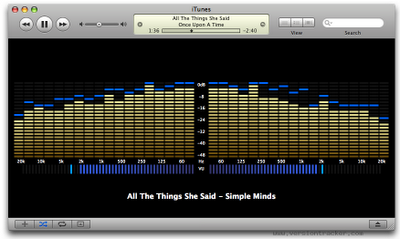
The Fourier transform converts a time-domain signal, like an audio wave, to a frequency-domain representation. For example, a spectrum analyzer (see figure below) is one application of the Fourier transform; and converserly the easiest method of implementing a spectrum analyzer is using DFT.
DFT is not just a one-way signal processing feature. Given a frequency domain representation, we can calculate the IDFT (Inverse DFT), to get back the time-domain signal. So, we can get some audio, transform into DFT, manipulate the frequencies (e.g. increase bass, decrease midrange, etc.) and then convert back to time-domain. It is dead easy to implement an equalizer using DFT!
In our case, we just want to build a lowpass filter, so we just have to wipe the frequencies we don't want, that is easy to do in the frequency domain. Note that a sharp removal of some range of frequencies is not a good filter, because it causes distortion. But it works, and it is ok for a simple demonstration.
Executing DFT and IDFT just to filter a signal seems wasteful. Indeed a FIR filter needs less processing power, and it is normally the #1 choice. But a DFT filter is easier to understand, and knowing the DFT filter first is important to understand the FIR filter.
For this article, I will use a female singer's voice that I really like: Núbia Lafayette. Another reason I used this particular sample is that I own the CD, so nobody can complain about piracy etc. Let's hear the original audio:
Now, the filtered version (1000-4000Hz bandpass filter), that sounds like a pocket radio:
And the code that does the trick (link to download):
#!/usr/bin/env python

LOWPASS = 4000 # Hz
HIGHPASS = 1000 # Hz
SAMPLE_RATE = 44100 # Hz

import wave, struct, math
from numpy import fft
FFT_LENGTH = 2048

# The higher the better, but this seems enough
OVERLAP = 512

FFT_SAMPLE = FFT_LENGTH - OVERLAP

# Nyquist rate = bandwidth available for a given sample rate
NYQUIST_RATE = SAMPLE_RATE / 2.0

# Convert frequencies from Hz to our digital sampling units
LOWPASS /= (NYQUIST_RATE / (FFT_LENGTH / 2.0))
HIGHPASS /= (NYQUIST_RATE / (FFT_LENGTH / 2.0))

zeros = [ 0 for x in range(0, OVERLAP) ]

# Builds filter mask. Note that this filter is BAD, a
# good filter must have a smooth curve, respecting a
# dB/octave attenuation ramp!
mask = []
for f in range(0, FFT_LENGTH / 2 + 1):
    rampdown = 1.0
    if f > LOWPASS:
        rampdown = 0.0
    elif f < HIGHPASS:
        rampdown = 0.0
    mask.append(rampdown)

def bound(sample):
    # takes care of "burnt" samples, due some mistake in filter design
    if sample > 1.0:
        print "!",
        sample = 1.0
    elif sample < -1.0:
        print "!",
        sample = -1.0
    return sample

original = wave.open("NubiaCantaDalva.wav", "r")
filtered = wave.open("NubiaFiltered.wav", "w")
filtered.setnchannels(1)
filtered.setsampwidth(2)
filtered.setframerate(SAMPLE_RATE)

n = original.getnframes()
original = struct.unpack('%dh' % n, original.readframes(n))
# scale from 16-bit signed WAV to float
original = [s / 32768.0 for s in original]

saved_td = zeros

for pos in range(0, len(original), FFT_SAMPLE):
    time_sample = original[pos : pos + FFT_LENGTH]

    # convert frame to frequency domain representation
    frequency_domain = fft.fft(time_sample, FFT_LENGTH)
    l = len(frequency_domain)

    # mask positive frequencies (f[0] is DC component)
    for f in range(0, l/2+1):
        frequency_domain[f] *= mask[f]

    # mask negative frequencies
    # http://stackoverflow.com/questions/933088/clipping-fft-matrix
    for f in range(l-1, l/2, -1):
        cf = l - f
        frequency_domain[f] *= mask[cf]

    # convert frame back to time domain
    time_domain = fft.ifft(frequency_domain)

    # modified overlap-add logic: previously saved samples
    # prevail in the beginning, and they are ramped down
    # in favor of this frame's samples, to avoid 'clicks'
    # in either end of frame.
    for i in range(0, OVERLAP):
        time_domain[i] *= (i + 0.0) / OVERLAP
        time_domain[i] += saved_td[i] * (1.0 - (i + 0.00) / OVERLAP)

    # reserve last samples for the next frame
    saved_td = time_domain[FFT_SAMPLE:]
    # do not write reserved samples right now
    time_domain = time_domain[:FFT_SAMPLE]

    # scale back into WAV 16-bit and write
    time_domain = [ bound(sample) * 32767 for sample in time_domain ]
    filtered.writeframes(struct.pack('%dh' % len(time_domain),
                                     *time_domain))
There is one twist in this code that is worth mentioning. Since any filtering in frequency domain causes phase distortion, you can't just piggyback audio frames, because the audio waves will not transition smoothly from one frame to the next. A continuous wave in the original audio will have a different phase in every frame generated by the filter. There will be a sharp discontinuity in every frame, very annoying to hear. (If you don't believe me, you can just set OVERLAP to zero, re-run the code, and see what happens.)
Both textbook solutions for this (overlap-save and overlap-add) seem not to solve this problem. I added cross-fading of frames to the overlap-add method, and then it worked. The cross-fade dillutes the phase distortion.
The plain overlap-add method does work when the filter is well-designed. The definition of a "good" filter is, its impulse response (i.e the inverse Fourier transform of the filter) must be shorter than the overlap. Since our filter is a sharp notch, its impulse response is infinitely long.
If the filter cannot be fixed, then we must smooth things elsewhere. One alternative is the crossfaded overlap-add as we found out by trail and error. Another popular choice is to apply a window function to each sample, like the sinc function, that makes the sample fade in and out smoothly. (It basically pre-bakes the crossfade into each time-domain sample so it does not need to be cross-faded later.)
This code uses plain overlap-add plus the
window function. The result is similar, as you can hear:
(link to audio)
Another thing that must be remembered by anyone that wants to play with FFT, is that frequency representation is linear. For audio signals, we are accustomed to logarithmic spectrum analyzers that match the octaves in music. But FFT is linear. This means that the musical resolution of FFT is higher for low octaves. Using a FFT with resolution too low will distort treble sounds first.
FFT generates two frequency "lobes": positive and negative frequencies. This sounds very strange, because negative frequencies don't exist in the real world. DFT has this mathematical concept. In our filter, we had two choices: just wipe all negative frequencies (that reduces the audio volume by half), or filter both "lobes" in the same fashion, as we did.
The array generated by FFT consists of complex numbers. This sounds scary but it has a valid purpose: a single complex number can represent both amplitude and phase. For example, if we find 1+0j in the 3000Hz 'bar', it means that audio has a 3000Hz component with amplitiude 1.0 and in phase with cos(x). If the sample were 0.707+0.707j, it means that the 3000Hz component still has amplitude 1.0 (the modulus) but it is 45 degrees ahead of cos(x).
Some applications, for example the spectrum analyzer, care only about the signal strength, not about the signal phase. These applications can simplify the FFT by considering only the positive lobe and taking the absolute values of the complex samples (which are always real and non-negative).
A real signal, like audio, radio waves, or any other real-world wave, has a Fourier transform with even amplitude. This means that a signal with frequency "f", once transformed, shows up both at positive and negative lobes, at frequencies +f and −f.
(By the way, an "even" function has the property f(x)=f(−x).)
On the other hand, the transform of a real signal displays odd phase i.e. the phase of the negative lobe is the opposite of the positive lobe. (An "odd" funcion has the property f(x)=−f(−x)).
The mathematical reason is that a real signal can be understood as the sum of two complex conjugate signals. Straight from any calculus textbook, we have the following relationship between trigonometry and exponentials:
cos(2πft+θ) = (ei(2πft+θ) + e−i(2πft+θ)) / 2
where "f" is the frequency and θ is the phase.
Fourier showed that every signal can be constructed by a sum of sines and cosines, so the relationship above allows us to say that any signal can be understood as the sum of pairs of complex exponentials (each pair having their own values for "f" and θ).
The Fourier transform of
ei(2πft+θ)
is zero for every value except "f". At this singular point F(f), the complex value has phase θ and extremely high absolute value (it is an unit impulse) since the signal is a pure tone.
The transform of the conjugate e−i(2πft+θ) hsa a singular point at F(-f) with unit response as absolute value and negative phase θ.
In short, the absolute values of F(f) and F(-f) are the same, but their phases are opposites. This is the "face" of the transform of a real-valued signal, as we sought to demonstrate.
A complex signal can also be understood as the sum of exponentials in the form ei(2πft+θ) but it is not guaranteed the exponentials will come as conjugate pairs. Therefore, its Fourier transform has no obligatory symmetry across lobes.
If we desire that an inverse Fourier transform generates a purely real signal, we must take care the spectrum has even amplitude and odd phase. Otherwise, the result will be a complex signal that has no real-world representation. We can always hammer complex numbers into real ones by using only the real part or taking their absolute values, but this changes the sinal and may destroy it, so the result may be meaningless.
Complex signals don't exist in the real world, but they can exist in our imagination and inside a computer's memory. And they can be very useful. For example, the I/Q demodulation, used in modems and radios, yields a complex signal that represents the band of interest. This signal can be filtered and transformed as if it were a real signal.