 IoT: 315/433MHz remote control
IoT: 315/433MHz remote control
IoT: 315/433MHz remote control
In spite of new and better technologies like Zigbee, the good old 315/433MHz keyfobs are still useful and widely used in garage doors and home automation. They are cheap, work surprisingly well (if not very secure) and are easy to understand and tinker with.
In most parts of the world, the keyfobs are tuned to 433.92MHz. In some countries, it is 314.0MHz or 313.1MHz. Either way, this band has good range and penetration. In some jurisdictions, wideband modulation is not allowed for this band, so digital keyfobs tend to use narrowband modulations like ASK/OOK, ASK or FSK.
A long time ago, garage door keyfobs were purely analog, meaning they would easily be actuated by spurious signals from radio amateurs and even new TV stations. Currently, they are all digital. The simplest ones send a fixed code that can be factory-set or "learnt" from another keyfob.
Being digital, they are nicely resistant to interference. Resistance to code collision is generally high, it depends on the code length. A handful of chips e.g. EV1527, PT2262, HT12E, HT6P20 dominate the whole keyfob market.
The fixed-code keyfobs are still widely used, but they are easy prey for replay attacks. They are also unsuitable for shared facilities with hundreds of users (e.g. garage door of a commercial building) because there is no way to revoke individual keyfobs.
Rolling-code technologies deflect replay attacks by sending a differenty code at every transmission. A very popular chip is the HCS301, even though its crypto has already been broken.
The perfect solution is to use 2-way communication betweeen keyfob and station, like Zigbee keyfobs do, but they are less available, more expensive, and more difficult to work with (Zigbee is a nightmare from the interoperability standpoint).
We stuck to the fixed-code keyfobs since they are cheap and easy to tinker with. There is a wide range of Arduino OOK modules, all cheap and readily available. Security (or lack thereof) is not an issue for us because the 433MHz remote control does not drive anything critical here.
If you want to play with these guys, consider getting a cheap logical analyser. It helps a lot.

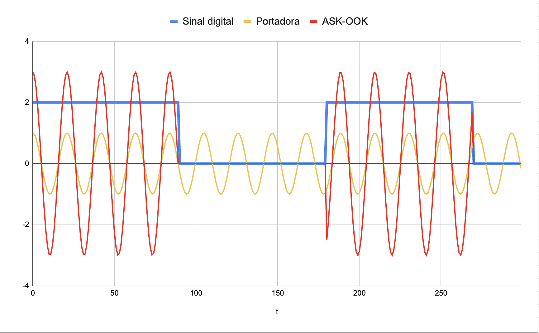
In the realm of fixed-code keyfobs, the ASK/OOK modulation is king. It means amplitude modulation / on-off keying. The transmitter can only transmit a fixed carrier, or be silent. Presence of carrier means "bit 1", absence of carrier means "bit 0". It is the digital equivalent of CW.
The OOK transmitter is dead simple, at the expense of a more complex receiver. The problem at RX side is to distinguish "bit 0" from "no transmission happening at all". Most receivers have AGC (automatic gain control). When there is no transmission, they increase the gain until something is received, and this "something" will be random noise.
In CW, the operator uses Morse code which is a sequence of dots and dashes whose duration is loosely known in advance by all parties. Likewise, ASK/OOK keyfobs employ chirp sequences, that is, bundles of physical bits that encode the logical bits of the code.
The chirp sequences are such that the receiver has a fair chance to distinguish signal from noise. The protocol of the chip EV1527 is:
The chip HT6P20, also widely used, has a similar protocol:
Other chips implement variations of the same theme. The source code of the Arduino rc-switch library is an invaluable reference to identify the protocol of an unknown keyfob.
Most if not all keyfobs send multiple copies of the code to increase the chance of successful reception, even if the button is pressed very briefly.
SYN480R and RXB-8 are two Arduino modules that can receive ASK/OOK signals. They are reasonably cheap and effective, the RXB-8 being more sensitive.
They handle all the radio stuff and have a single output pin that says "there is a carrier" or "there is no carrier". We can connect this pin directly to the signal analyser. The image below shows how the output looks like:
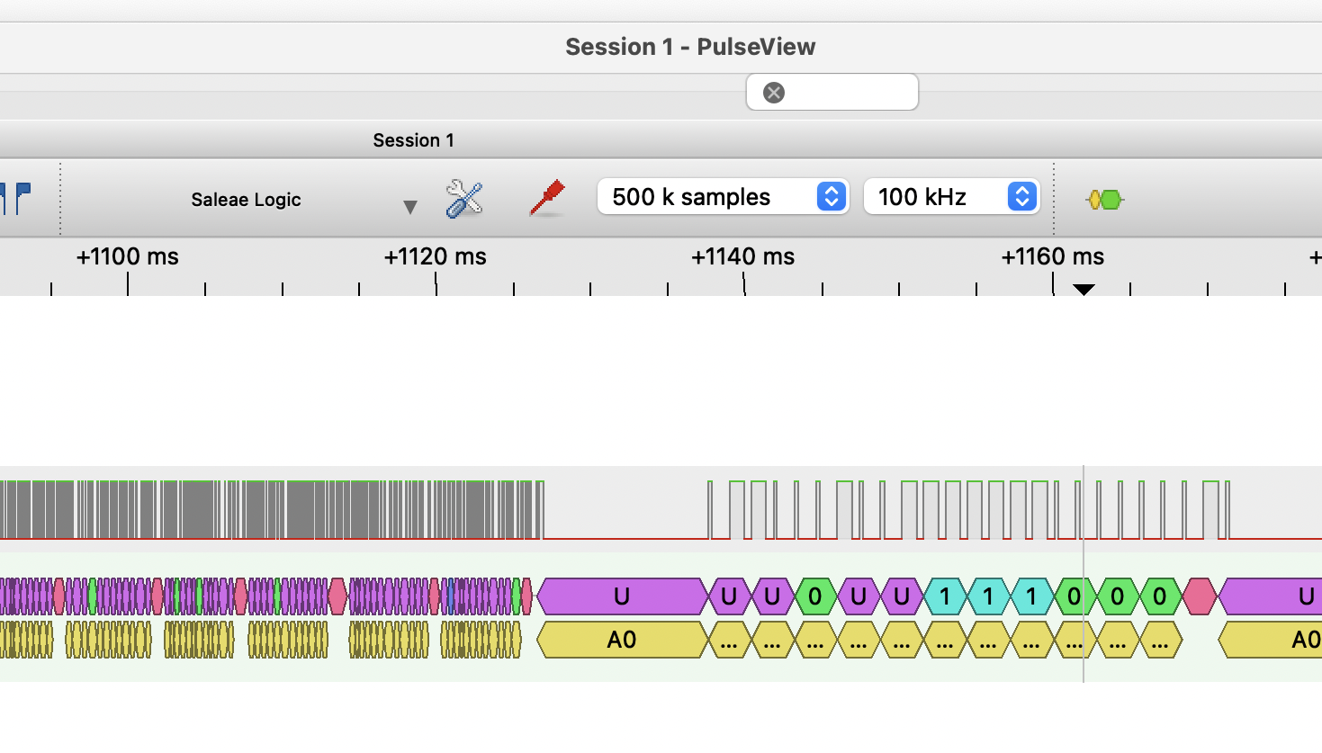
At the left side, we can see that, in the absence of a transmitter, the receiver cranks up the AGC and accepts noise. We know it is noise because it is high-frequency and visibly random. Around the time +1126ms, the keyfob sends the preamble that calibrates the AGC.
At right side, with AGC calibrated to the nearby transmitter, the receiver can distinguish a legit carrier from background noise, and the waveform is a regular chirp pattern (right side of the graph).
The long silence in the preamble is a simple and effective way to detect "start of packet", since it is almost impossible to happen by chance. The "end of packet" can be similarly detected by the post-transmission silence.
Chirps have a definite length range (between 200µs and 600µs for typical keyfobs). The decoder should check the chirps are within range, and also check they have uniform lengths within a packet. Otherwise, it is prone to "decode" noises sequences as legit code, and since noise is random, it will eventually collide with an expected code.
Unfortunately, no keyfob I know of sends CRC codes, not even parity codes, to check packet integrity. The HT6P20 sends a fixed-value suffix that does help to catch some errors. The PT2262 chip has a nice scheme of "tribit" encoding i.e. 2 bits represent 3 possible values and the 4th is forbidden.
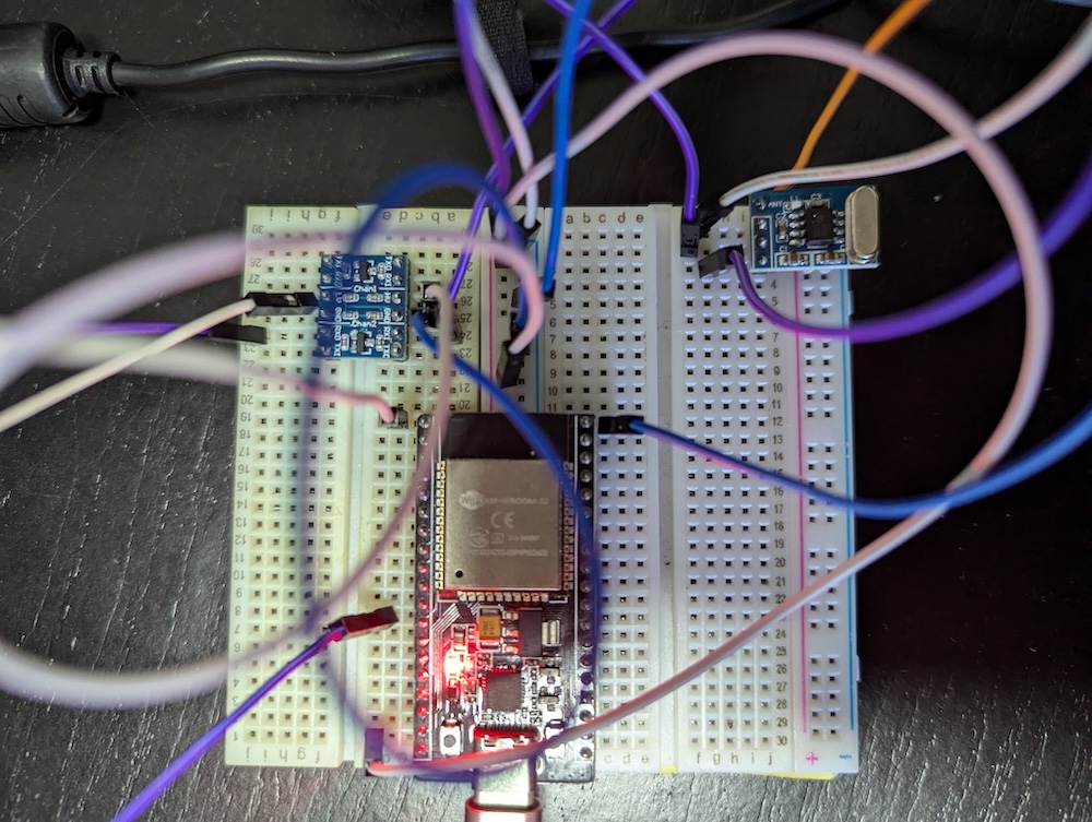
Trivia: the RX modules are said to work in either 3.3V or 5V, but they do better with 5V. This means you need a level converter between the module and the ESP32 for the data pin. Not every converter works; bidirectional converters tend not to, at least in my experience. Unidirectional level converters or simple resistor dividers are best.
Receivers like the SYN480R and RXB-8 are dumb; they just indicate the presence or absence of a radio carrier. The OOK decoding proper must be implemented elsewhere.
The baud rate of OOK keyfobs is low enough to allow for software decoding on a microcontroller. Besides being a nice little challenge, software-based decoding makes it easy to support a wider range of keyfobs.
But, if you don't want to bother, there are self-contained receiver+decoder modules like the RX480E. People in the garage door business use this module to retrofit digital keyfobs on older analog systems. The output of this module means "code detected", which can be hooked up directly to the controlled device or to a microcontroller.
Of course we went the software route and reinvented the wheel instead of using libraries like VirtualWire or RC switch. To make things more interesting, we employed MicroPython, which is a bit slow for the task, even running on an ESP32.
Almost every implementation of OOK decoder follows this strategy:
Our first bottom-half decoder uses interrupts, in order to try to be as efficient as possible. But using interrupts in MicroPython is not free, either: the interrupt handlers must work fast and cannot allocate memory.
The interrupt handler is set to detect signal transitions i.e. it is called when the raw digital input goes from low to high or vice-versa. We timestamp each call in order to measure how long each logic level was held.
Because of this, the interrupt handler must have low jitter. Jitter is the variation of delay. There always will be a delay between the hardware event and the call to handler, but this delay should be always the same. In MicroPython/ESP32, the jitter is ~25µs (unless Wi-Fi is active, as we will see soon).
Since we are measuring chirp lengths no smaller than 150µs, it is good enough, for now.
The upper-half decoder handles the output from the low-level decoder. Currently, it implements the protocols EV1527 and HT6P20. Since it wants a file as input, it is written to run on a computer, not on the ESP32. If you don't have any keyfob-related hardware, you still can test the upper-half decoder with these sample sequences.
Once we played enough with the two decoders and were happy with their performance, we put them together in the script sniffer.py. This one can run on ESP32 and does the job end-to-end, being a capable keyfob sniffer if you like.
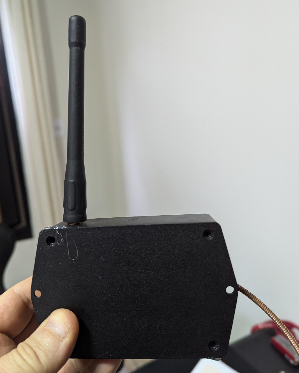
What about range and sensitivity? The biggest factor is the antenna. Any wire attached to the ANT pin of the receiver module will do, but the optimal length is 17cm for 433MHz. If the antenna must be apart from the receiver, a ready-made antenna with coaxial cable as transmission line is the best.
In my home automation framework, I use MQTT to communicate between all IoT boxes. The endgame here is to have a 433MHz box that publishes some MQTT topic when a keyfob is detected. Of course, another box subscribes to the same topic and reacts accordingly when the right code is received.
The meat of the code for the 433MHz box can be found here. The commit history corroborates the story we will tell next.
The first hurdle: the standalone decoder (cited in the previous section) refused to work well as soon as it was integrated into our framework. Only one in ten keyfob presses were detected. Why was that? We found that, in MicroPython ESP32, activating Wi-Fi increases dramatically the jitter of the interrupt handler. It gets as high as 500µs.
This is a known issue of the ESP32 port of MicroPython. One workaround would be to use a dedicated ESP32 for the bottom-half decoding (assuming we insist on using MicroPython end-to-end). Another way is not to use interrupts and appeal to a busy loop.
Busy loops are ugly and there were no guarantees it would do any better. But it did actually work well, restoring the jitter to 25µs, meaning this jitter is inherent to the interpreter, not only to a interrupt handler.
At this point, we had a working receiver with MQTT integration that fulfilled the intrinsic objective of the project.
The ESP32 microcontroller has a feature named RMT, originally designed to interface with infrared remote controls. It allows to offload almost the whole "bottom-half" of the OOK decoder to the hardware, freeing the CPU and avoiding the need of busy loops.
Unfortunately, the current port of MicroPython to ESP32 gives access to the TX side of RMT, not to the RX side. For our own use, we implemented RMT RX support and it works beautifully. In order to have it accepted upstream, we need to update the current RMT TX support to the latest ESP-IDF API. We put together a PR for that, too, which is pending approval.
The RX modules we have been using e.g. SYN480R and RXB-8 are quite handy because they handle all the radio stuff for us. They deliver a single digital output indicating presence of absence of a radio carrier.
But what if we want to meddle with the analog radio side of things? One possibility is to use SDR — Software-Defined Radio. It is an universal radio receiver that delegates demodulation to software. The most well-known device of this class is the RTL-SDR. (There are better SDRs, but they are much more expensive.)
TL;DR our working keyfob receiver using RTL-SDR is here: a Bash script that calls the Python main script. If you plan to run this, clone the whole repository since the main script imports some auxiliary modules from there.
Our intention here is not to create a "finished product" like we did for the ESP32 version. This is just for kicks and it is meant to run on a Linux PC or Mac. And yes, I know there are excellent ready-made software that does the very same thing.
In order to demodulate a 433MHz signal in software, in principle we need a sampling rate 2× bigger, ideally 4× bigger. Since a 1600MHz sampling rate is too much for a PC to handle, most SDRs don't do direct sampling. Instead, they translate the band of interest to baseband, which can be sampled in a lower rate.
The sampling rate of the baseband has twofold importance. It determines the workload of the software demodulator, and also defines the signal bandwidth. By the Nyquist theorem, a sampling rate of 200kHz delivers a bandwidth of 100kHz. If it is a complex signal, it delivers 200kHz total (−100kHz to +100kHz). We should use a higher sampling rate than strictly necessary and then apply a low-pass filter, since sampling introduces distortions at the extreme ends of the band.
In our particular case, we are interested in a 200kHz band around the frequency 433.92MHz. We need to "listen" to all this bandwidth since keyfobs are not very precise in frequency. The RTL-SDR does not accept sampling rates between 300kHz and 900kHz, so we splurged a bit and selected a rate of 960kHz.
To keep the main script as simple as possible, we use the RTL-SDR CLI tool to drive the radio and pipe the I/Q samples:
rtl_sdr -f 433920000 -g $GAIN -s 960k - | ./ook_433.py
In general, SDRs employ complex demodulation and deliver a baseband signal composed of complex numbers. A full explanation can be found here. The general idea is, the complex demodulator is a Swiss-army knife and can be the front-end for every possible radio technology.
The output of rtl_sdr is a sequence of I/Q samples i.e. a sequence of complex numbers. Each complex number is composed of 2 bytes, with bias of 127.4 and scaling 128.0. For example, a sample with raw values (128, 125) is actually worth 0.0046875-0.01875j.
NumPy is very handy to do this kind of conversion tersely and efficiently:
    # Parse RTL-SDR I/Q format
    iqdata = numpy.frombuffer(data, dtype=numpy.uint8)
    iqdata = iqdata - 127.4
    iqdata = iqdata / 128.0
    iqdata = iqdata.view(complex)
Our sampling rate is 960kHz but we only want to feel a 200kHz bandwidth, so we apply a digital lowpass filter:
INPUT_RATE = 960000
BANDWIDTH = 200000
...
if_filter = filters.low_pass(INPUT_RATE, BANDWIDTH / 2, 48)
    ...
    iqdata = if_filter.feed(iqdata)
We divide BANDWIDTH by two since a complex baseband signal carries negative frequencies. A filter with 100kHz cutoff will pass a band between −100kHz to +100kHz, grand total 200kHz as we wished.
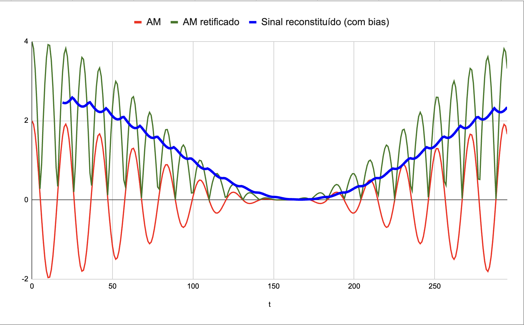
In AM radio modulation (almost extinct but historically important), the original content (generally audio) can be extracted by following the contour of the radio signal. This is the basis of the "envelope detector", that can be implemented with one rectifier diode and one capacitor.
(This is neither the only nor the best way to demodulate AM. But it is the cheapest, and can even be improvised by using a rusty razor as rectifier.)
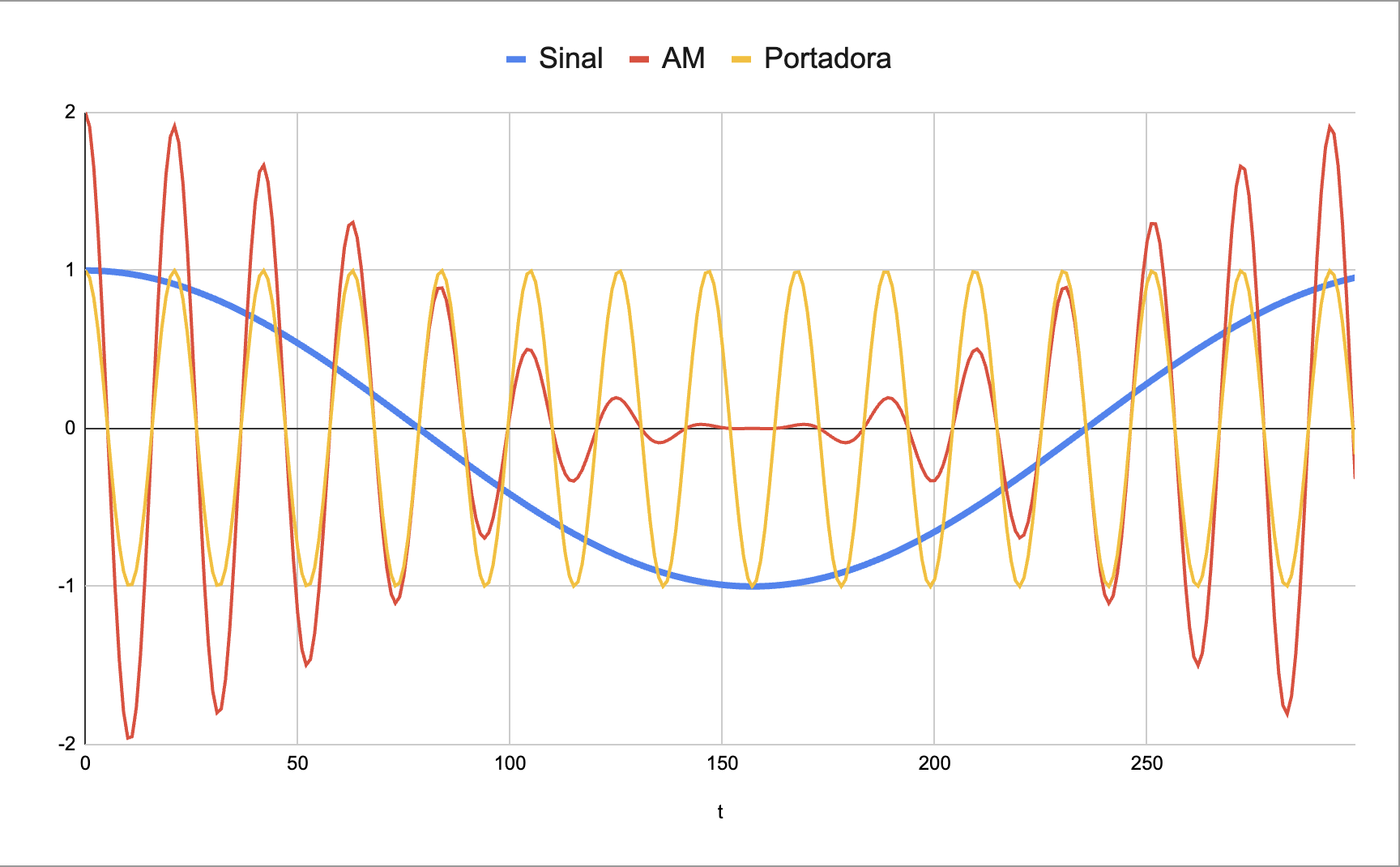
The ASK/OOK modulation is conceptually similar, but even simpler, because the content has only two possible values: on and off.
This is our software implementation of the envelope detector:
TRANS_MIN_US = 150
...
PREAMBLE_MIN_US = 5000
...
GLITCH_US = min(TRANS_MIN_US, PREAMBLE_MIN_US) / 4
...
envelope_filter = filters.low_pass(INPUT_RATE, 1000000 / GLITCH_US)
    ...
    iqdata = numpy.absolute(iqdata)
    # Detect envelope using a low-pass filter
    iqdata = envelope_filter.feed(iqdata)
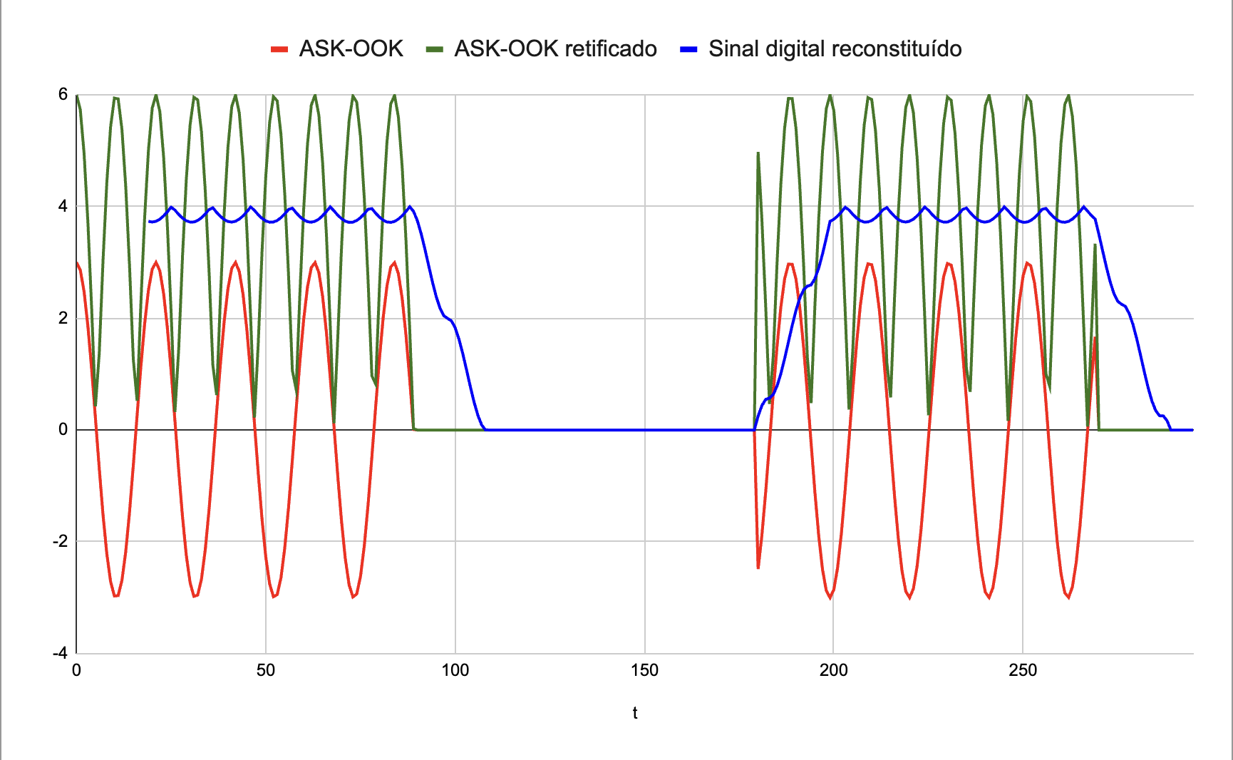
The function numpy.absolute() is our software rectifier and casts the complex signal down to real positive numbers. This "destroys" the signal, but it doesn't matter because we only want to measure its strength.
The cutoff frequency of the lowpass filter is a compromise between a flat envelope when there is a carrier, and prompt transition at the transition edges. GLITCH_US is a time value; logic levels shorter than this are transients we don't need to see.
Why not configure the filter using TRANS_MIN_US which is the shortest valid logic level? Fact is, we need to let some high-frequency noise to pass, since it makes it easier for the OOK receiver to distinguish between legit signal and random noise.
At this point, the signal extracted from SDR is almost the same as we get from an OOK receiver module, except it is still analog. We need to establish a cutoff level so it can be converted to digital.
In our implementation, we have this variable bgnoise that is a moving average of background noise. We assume the keyfob signals are seldom received, and we are listening to pure background noise most of the time. We consider that a signal "n" times above background noise is level "high", otherwise it is level "low".
For this scheme to work well, the gain of the RTL-SDR must be set to a fixed value e.g. 40dB. Using AGC would make bgnoise to settle in a higher value, making the decoder to ignore weaker signals. If we wanted to run it with AGC, we'd need to improve the overall algorithm.
From that point on, the OOK decoder is no different from the ones we implemented for ESP32. The code is almost identical.
Objectively speaking, it can't. The OOK modules for Arduino have sensitivity between -106dBm and -114dBm. RTL-SDR's sensitivity is around -95dBm. This difference means eight times less range. The fun of using an SDR is to be able to tweak all parameters of the receiver pipeline, so we can better understand how a "black box" receiver does its magic.
In our tests, the SDR worked even better than expected — it caught around 50% of the keyfob actuations that were detected by the kosher receiver. The SDR was hooked to a 2m monopole antenna in the attic, plus 45ft of RG-58 cable, so it is a mixed bag of good height, bad SWR and 5dB cable losses.
SDRs tend to admit out-of-band radio signals as noise, which reduces their SNR sensitivity. A simple and effective solution is to insert a bandpass filter. With a 433MHz filter, our SDR receiver could catch 95% of the actuations. So, if you plan to use SDR seriously, make sure to use RF filters.
Our intrinsic objective is to use keyfobs for home automation. So, we purchased keyfobs and RX modules. But the SYN480R module was bundled with the SYN115 TX module, for free, so why not? Transmitting is easier than receiving, since we just need to follow the protocol blindly.
To start with, we put together an "upper half" TX script. It is "upper half" since it just encodes data into a chirp sequence. The idea was to test generated sequences against our existing upper-half receiver, before touching the hardware.
By the way, this is a slightly modified version of the upper-half decocder. It accepts data via stdin, not from a file.
The SYN115 module is the exact inverse of the SYN480R, having a single digital input pin that turns the carrier on and off. One important difference: it is 3.3V, so no need of a level converter if you are using ESP32 or RP2040. Consumption is low so it can feed off the MCU 3.3V regulator.
Here we can finally use the ESP32 RMT feature, since MicroPython gives access to the transmission features. This spares us from bitbanging the output. Just send a list of logic levels to RMT, and it does the rest. Here is the complete TX script.
We found it is advisable to send the code twice or thrice (exactly like the keyfobs do) otherwise the receiver tends to lose messages. It seems to be a trait of all OOK receivers. We used the TX script to operate our garage door, and it also misses actuations that send the a single copy of the code, so it is not a problem in our software or in our RX modules.
Since the RMT output has high precision (12.5ns) the software-based transmitter was a good tool to gauge the jitter of the receiver scripts, discussed previously. That's how we found the 25µs number.
The module TX118SA-4 is the transmitter counterpart of the RX480E. Both are offered by the same manufacturer (QIACHIP). It is a "black box transmitter" that emulates an EV1527 keyfob and has 4 digital inputs that emulate the 4 buttons of a typical keyfob. The module can be actuated by a microcontroller or by a simple momentary switch.
As far as we know, the code it sends is factory-set and not programmable. People that work with garage doors hook this module to the car's high-beam handle, so the door can be operated "handsfree". It works with a wide range of voltages, from 3V to 24V.
Since it came along with other modules in the same package, we just had to test this guy. We used it as a beacon to measure range. This simple script drives a TX118SA-4 every 10 seconds. Note the script was written for the ESP8266 and uses the pin 2, which is inverse logic in the NodeMCU.