 Python FM - listening to radio with Python
Python FM - listening to radio with Python
Python FM - listening to radio with Python
In our articles about FM and AM, we implemented modulation in software, but the "transmission medium" was... audio files. That was all we could do in 2010, but a question remained: do these techniques really work with real radio signals?
Well, we are in 2019, and SDR (software-defined radio) dongles are all over the place. We can finally put our code to test, at least for receiving. TX-capable SDRs are still pretty expensive, so a transmission test will have to wait some years more.

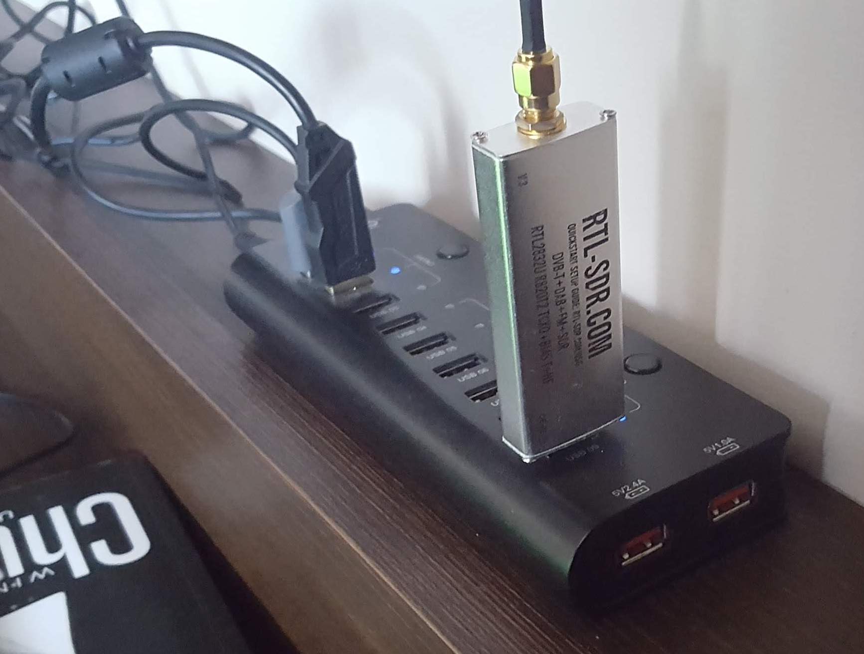
Most RX-only, affordable SDRs in market are clones of the original RTL-SDR product. The clones do work fine, but I recommend the original. The build is better, it is more sensitive, it has a TCXO, the included dipole antenna is very good. And the price difference is not big.
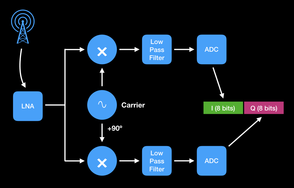
Whatever the mode (AM, SSB, FM, digital), demodulation starts by moving or translating the radio band of interest to low-frequency baseband. This translation, known as the front-end, is generally carried out by by "mixing" i.e. multiplying the radio signal by a locally generated carrier. The SDR does the front-end, converts the baseband result to digital samples, and delivers it to software.
RTL-SDR is a homodyne or direct conversion receiver: it translates the radio signal to baseband in a single mixing. Analog receivers and high-quality SDRs are heterodyne or double conversion: they mix to some intermediate frequency (455kHz is a common choice for radio), them mix down to baseband. This allows for better filtering between mixes. Some radios even do triple conversion.
Some modes need the signal to be mixed by two versions of the same carrier, phased by 90º, in order to extract phase information. This is known as quadrature or I/Q demodulation, which is implemented by RTL-SDR. The I/Q demodulator is sort of a "universal receiver" and can serve as a front-end of almost any mode. (Likewise, an I/Q modulator is an "universal transmitter".)
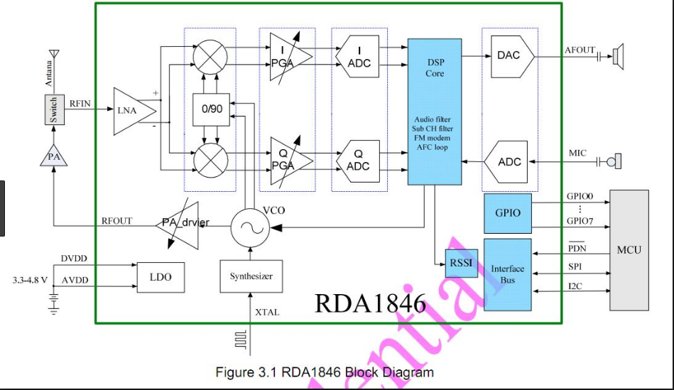
The SDR techniques are not restricted to SDR dongles. Many low-cost HT transceivers use them, generally at receiver side.
When we start the RTL-SDR receiver, we need to supply at least two parameters: carrier and sampling rate. For example, the command below asks for a 121MHz carrier and a sample rate of 1920k samples per second:
rtl_sdr -f 121M -s 1920k sample.rtl
The SDR filters the signal to avoid sampling aliasing, therefore the sampling rate also limits the bandwidth. In the example above, we are capturing a 1.92MHz band centered at 121Mhz (120.04MHz to 121.96MHz). Since the filtering is not perfect, the "clean" bandwidth is about 80% of the sampling rate (in the case, 120.20MHz to 121.80Mhz).
RTL-SDR sample precision is 8 bits. Each sample is a tuple of two values: I and Q. A sample rate of 1920k implies a data rate of 3.84MB/s. Individual values go from -127.5 to +127.5, offset by 127.5 so they fit in an integer byte. (Which means negative values are not expressed in two-complement.)
The Python and shell scripts mentioned in this text can be found in this GitHub repository.
In this text about FM modulation, the receiver front-end is I/Q demodulation followed by low-pass filtering. The SDR does both things, so our "Python radio" doesn't need a front-end. All we need to do is to tune the RTL-SDR carrier on radio frequency, and use a sampling rate low enough to fit a single station.
Excerpt from python_fm_mono:
rtl_sdr -f 89.5M -s 256k -n 2560000 teste.iq
cat teste.iq | ./fm1.py > teste.raw
sox -t raw -r 256000 -b 16 -c 1 -L -e signed-integer teste.raw \
	-d rate 32000
RTL-SDR has an important limitation: sampling rate must be either lower than 300k or bigger than 900k. If we want a bandwidth of e.g. 500kHz, we must capture a wider band and filter by software. This is not a problem if we want to listen a single FM station, whose bandwidth is 200kHz, safely below 300k.
When the receiver front-end is I/Q, and the carrier is centered on FM station frequency, the signal frequency deviations can be detected as phase variations. The absolute phase does not matter; it is the rate of variation or phase rotation that interests us.
Moreover, the strength of the signal is not important. Just the relationship between I and Q are important for FM. (The exact opposite happens in AM detection: the raw material for audio detection is the sum of I and Q.)
The Python script fm1.py implements a minimally viable FM receiver that ingests SDR samples and spits audio samples.
The script python_fm_mono records 10 seconds worth of SDR samples into an audio file. The script python_fm_rt plays radio in real time, provided the computer is fast enough.
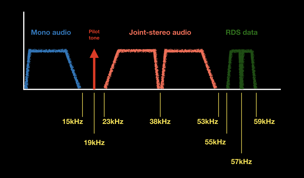
The FM "audio" has a very large bandwidth (75-100kHz), but the mono audio is limited to 15kHz. The ultrasonic part can carry extra information, depending on region and station.
The script fm1s.py implements a FM stereo decoder (sorry, no RDS yet). The scripts python_fm_stereo and python_fm_rt_stereo start RTL-SDR and forward samples to Python.
The implementation of stereo decoding in sofware was a piece of work...
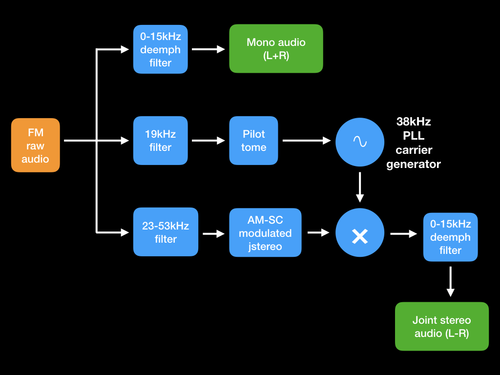
As we tried to explain in this article about AM, decoding AM-SC is difficult, because we need to generate an exact replica of the transmitter's carrier at receiver side, both in frequency and phase. To aid in this generation, stereo FM sends a 19kHz pilot tone. Stereo and RDS carriers are in-phase multiples of the pilot tone.
The usual method of generating the local carrier is the PLL (Phase-Locked Loop) with zero-crossing detection. The idea is, when the pilot tone changes polarity, being a cosine function, its phase is either 90º or 270º. At these moments, the local carrier should be at 180º.
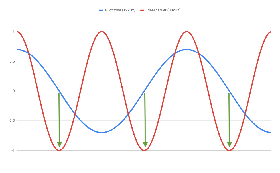
As we find our carrier is "rushing" or "dragging" in relation to the pilot tone, we adjust the frequency. The trick is to make these adjustments fast enough while avoiding a runaway oscillation.
The first thing is to isolate the pilot tone with a notch filter. We also need filters to isolate the mono signal, the modulated stereo signal, and the demodulated result. The FIR filters can be found at filters.py. I had a NIH itch and wrote the filters myself, but the SciPy package has filters out-of-the-box.
By the way, it is NOT ok to simply generate a freewheeling 38kHz carrier. Neither your computer nor the FM station has 100% precise clocks, so their carriers will drift, spoiling the stereo signal. Yes, I have tried this way, and the stereo sound kept fading in and out as the local carrier went in and out of phase.
But yes, you can trust the pilot tone to be pretty close to 19kHz. (I think the allowed deviation is no bigger than 5Hz.) If you are debugging your PLL implementation and it gets out of sync, it is certainly a bug in your code, not a problem at the FM station.
Perhaps someone will note the mono FM receiver has too much treble. In the stereo version, the audio is low-pass filtered to 15kHz, and it is also "deemphasized". Deemphasis is a low-pass filter with very gentle ramp (10dB across the band).
This is necessary because FM stations "emphasize" the audio, that is, they boost treble using a 10dB ramp. In FM mode, the background noise increases linearly with frequency, and treble boosting compensates for that. (Vinyl LPs employ the same technique for similar reason.)
Emphasizing/deemphasizing is legacy technology, 80 years old or so, and people liked to use baroque definitions back then. In theory, emphasis is defined as the time constant of the hypothetical emphasis RC filter. For example, an emphasis of 75µs (the standard in the Americas) means a cutoff (-3dB) frequency of around 2100Hz.
Such a baroque definition is a bit confusing and leaves room for interesting interpretations. An RC filter has a ramp of 6dB/octave, which means a ramp of 15dB between 2100 and 15000Hz. In pratice, a 10dB ramp is used. Even the time constant is different in every region (it is 50µs in Europe). Every FM radio manufacturer uses a slightly different deemphasis filter to achieve a "better" sound.
The first FM stations were mono. When stereo was introduced, it had to be backward compatible. Being in the ultrasonic range, the stereo sub-band is inaudible and possibly filtered out.
The 0-15Khz mono signal is the sum of left and right channels (L+R). This is what a mono listener expects to hear. The 23-53kHz sub-band carries the difference between channels (L-R). This technique is known as joint-stereo and it is also used in MP3 files.
The receiver reconstitutes the L and R channels by adding and subtracting the mono and joint-stereo signals:
Since the FM audio band is 75-100kHz, we must not skimp on SDR data rate. We use 256k up to joint-stereo detection. The final audio samples are downsampled to 32k, since FM audio is not expected to go beyond 15kHz.
256k:32k is an 8:1 relationship. Downsampling can be carried out by simple decimation, that is, use 1 every 8 samples. The only catch is, the signal must be pre-filtered so it fits in the new bandwidth. But we already did this when deemphasis filter was applied.
BTW, upsampling by 1:N is equally simple. For example, to go from 32k to 256k, we just stuff seven zero samples along with every original sample, and filter the result to remove the artifacts above 16kHz. To do M:N resampling (e.g. 32k to 48k would be 2:3) we can upsample 1:3 then downsample 2:1. The post-upsampling and pre-downsampling filters can be combined into one and it can be further optimized using the polyphase technique.
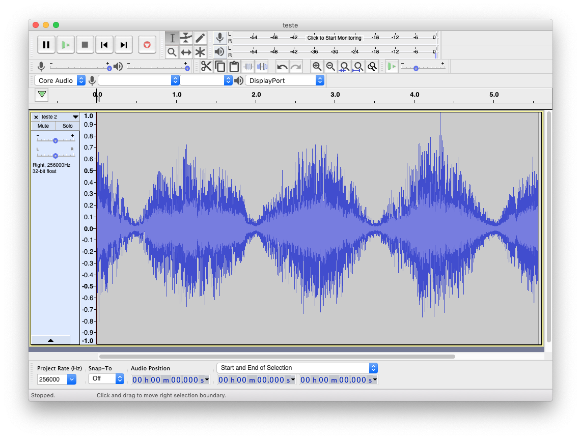
Every debug session took a lot of listening and checking audio files on Audacity. The most complicated component is the PLL. Since it is not always easy to find by ear that stereo separation was lost, I have added a debug mode (-d) which records 3 audio channels: raw mono (L+R), stereo diff (L-R) and pilot tone. When the PLL is bad, the stereo diff audio keeps fading in and out, making it easy to find.
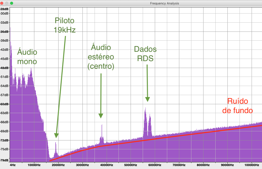
In debug mode, no downsampling takes place and audio is recorded at 256k samples. Mono channel is not low-pass filtered; it is still 'raw' audio, so it is possible to find all sub-bands (mono, stereo, pilot tone, RDS) in the spectrum.
In general, the "Python FM" code style privileges clarity over speed. The mono version is particularly minimalistic. (Using NumPy gives a big speed boost without sacrificing clarity.)
Unfortunately, the pure-Python stereo version could not play in real time, so I had to resort to Cython. The script can be run in two modes: pure Python or using the Cython module, passing the -o parameter (you need to compile the module before use).
At the moment, the Cython version uses 50% of a single CPU, so yeah, there is a lot of room for improvement.
Stereo decoding should only be activated when the pilot tone is detected.
DC (very low Hz) signal removal without sacrificing bass.
RDS text data: decoding and printing.